
Datasheet


AD7306
–8–
REV. B
C1624a–2–8/94
PRINTED IN U.S.A.
OUTLINE DIMENSIONS
Dimensions shown in inches and (mm).
Single-Ended Data Transmission
Single-ended interfaces are used for low speed, short distance
communications such as from a computer terminal to a printer.
A single line is used to carry the signal. Various standards have
been developed to standardize the communication link, the most
popular of these being the RS-232. The RS-232 standard was
introduced in 1962 by the EIA and has been widely used
throughout the industry. The standard has been revised several
times, and the current revision is known as EIA-232E. The
RS-232 standard is suitable for single-ended data transmission
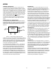
at relatively slow data rates over short distances. A typical
RS-232 interface is shown in Figure 14.
RS-232 CHANNEL
DATA
IN
DATA
OUT
RX
TX
Figure 14. Single-Ended RS-232 Interface
Differential Data Transmission
When transmitting at high data rates, over long distances and
through noisy environments, single-ended data transmission is
often inadequate. In this type of application, differential data
transmission offers superior performance. Differential transmis-
sion uses two signal lines to transmit data. It rejects ground
shifts and is insensitive to noise signals which appear as com-
mon mode voltages on the transmission lines. To accommodate
faster data communication, the differential RS-422 standard was
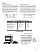
developed. Therefore, it can be used to reliably transmit data at
higher speeds and over longer distances than single-ended trans-
mission. A typical RS-422 interface is shown in Figure 15.
RS-422 CHANNEL
DATA
IN
DATA
OUT
RX
TX
Figure 15. Differential RS-422 Interface
Table I. Comparison of RS-232 and RS-422 Interface Standards
Specification EIA-232E RS-422
Transmission Type Single-Ended Differential
Maximum Data Rate 20 kB/s 10 MB/s
Maximum Cable Length Load Dependent 4000 ft.
Minimum Driver Output Voltage ±5 V ±1.5 V
Slew Rate 30 V/µs max
Receiver Input Resistance 3 kΩ to 7 kΩ 4 kΩ min
Receiver Input Sensitivity ±3 V ±200 mV
Receiver Input Voltage Range ±15 V ±7 V
No. of Drivers per Line 1 1
No. of Receivers per Line 1 10
24-Lead SOIC (R-24)
24 13
121
0.6141 (15.60)
0.5985 (15.20)
0.4193 (10.65)
0.3937 (10.00)
0.2992 (7.60)
0.2914 (7.40)
PIN 1
SEATING
PLANE
0.0118 (0.30)
0.0040 (0.10)
0.0192 (0.49)
0.0138 (0.35)
0.1043 (2.65)
0.0926 (2.35)
0.0500
(1.27)
BSC
0.0125 (0.32)
0.0091 (0.23)
0.0500 (1.27)
0.0157 (0.40)
8°
0°
0.0291 (0.74)
0.0098 (0.25)
x 45°
24-Lead Pin Plastic DIP (N-24)
0.260 ± 0.001
(6.61 ± 0.03)
0° - 15°
0.11 (2.79)
0.09 (2.28)
SEATING
PLANE
1.228 (31.19)
1.226 (31.14)
0.02 (0.5)
0.016 (0.41)
0.07(1.78)
0.05 (1.27)
0.130 (3.30)
0.128 (3.25)
0.32 (8.128)
0.30 (7.62)
0.011 (0.28)
0.009 (0.23)
NOTES
1.
2.
LEAD NO. 1 IDENTIFIED BY DOT OR NOTCH.
PLASTIC LEADS WILL BE EITHER SOLDER DIPPED OR TIN LEAD PLATED
IN ACCORDANCE WITH MIL-M-385 10 REQUIREMENTS.