
Datasheet

AD736
REV. C
–8–
C1174a–10–9/88
PRINTED IN U.S.A.
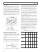
The input coupling capacitor, C
C
, in conjunction with the 8 kΩ
internal input scaling resistor, determine the –3 dB low fre-
quency rolloff. This frequency, F
L
, is equal to:
F
L
=
1
2π(8,000)(TheValue of C
C
in Farads)
Note that at F
L
, the amplitude error will be approximately
–30% (–3 dB) of reading. To reduce this error to 0.5% of read-
ing, choose a value of C
C
that sets F
L
at one tenth the lowest
frequency to be measured.
In addition, if the input voltage has more than 100 mV of dc
offset, than the ac coupling network shown in Figure 21 should
be used in addition to capacitor C
C
.
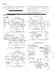
Applications Circuits
Figure 19. AD736 with a High Impedance Input Attenuator
Figure 20. Differential Input Connection
Figure 21. External Output V
OS
Adjustment
Figure 22. Battery Powered Option
Figure 23. Low Z, AC Coupled Input Connection
OUTLINE DIMENSIONS
Dimensions shown in inches and (mm).