
Datasheet


AD736 Data Sheet
Rev. I | Page 10 of 20
THEORY OF OPERATION
AC COUPLED
C
C =
10µF
8kΩ
00834-017
INPUT
AMPLIFIER
I
B
<
10pA
FULL-WAVE
RECTIFIER
RMS
TRANSLINEAR
CORE
−VS CAV
+V
S
COM
1
2
3
4
VIN
5
CAV
33
µ
F
C
F
OUTPUT
6
7
CF
8
+
+
8k
Ω
(
OPTIONAL LPF
)
DC
+
COUPLED
AD736
0.1
µ
F
TO COM PIN
0.1
µ
F
10
µ
F
OUTPUT
AMPLIFIER
BIAS
SECTION
C
C
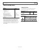
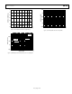
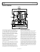
Figure 18. AD736 True RMS Circuit
As shown by Figure 18, the AD736 has five functional
subsections: the input amplifier, full-wave rectifier (FWR), rms
core, output amplifier, and bias section. The FET input amplifier
allows both a high impedance, buffered input (Pin 2) and a
low impedance, wide dynamic range input (Pin 1). The high
impedance input, with its low input bias current, is well suited
for use with high impedance input attenuators.
The output of the input amplifier drives a full-wave precision
rectifier that, in turn, drives the rms core. The essential rms
operations of squaring, averaging, and square rooting are
performed in the core using an external averaging capacitor,
C
AV
. Without C
AV
, the rectified input signal travels through the
core unprocessed, as is done with the average responding
connection (see Figure 19).
A final subsection, an output amplifier, buffers the output from
the core and allows optional low-pass filtering to be performed
via the external capacitor, C
F
, which is connected across the
feedback path of the amplifier. In the average responding
connection, this is where all of the averaging is carried out.
In the rms circuit, this additional filtering stage helps reduce any
output ripple that was not removed by the averaging capacitor, C
AV
.
TYPES OF AC MEASUREMENT
The AD736 is capable of measuring ac signals by operating as
either an average responding converter or a true rms-to-dc
converter. As its name implies, an average responding converter
computes the average absolute value of an ac (or ac and dc)
voltage or current by full-wave rectifying and low-pass filtering
the input signal; this approximates the average. The resulting
output, a dc average level, is scaled by adding (or reducing)
gain; this scale factor converts the dc average reading to an rms
equivalent value for the waveform being measured. For example,
the average absolute value of a sine wave voltage is 0.636 times
V
PEAK
; the corresponding rms value is 0.707 × V
PEAK
. Therefore, for
sine wave voltages, the required scale factor is 1.11 (0.707/0.636).
In contrast to measuring the average value, true rms measurement
is a universal language among waveforms, allowing the magnitudes
of all types of voltage (or current) waveforms to be compared to
one another and to dc. RMS is a direct measure of the power or
heating value of an ac voltage compared to that of a dc voltage;
an ac signal of 1 V rms produces the same amount of heat in a
resistor as a 1 V dc signal.