
Datasheet


AD736 Data Sheet
Rev. I | Page 2 of 20
TABLE OF CONTENTS
Features .............................................................................................. 1
General Description ......................................................................... 1
Functional Block Diagram .............................................................. 1
Product Highlights ........................................................................... 1
Revision History ............................................................................... 2
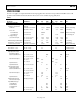
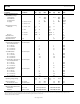
Specifications ..................................................................................... 3
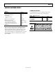
Absolute Maximum Ratings ............................................................ 5
Thermal Resistance ...................................................................... 5
ESD Caution .................................................................................. 5
Pin Configuration and Function Descriptions ............................. 6
Typical Performance Characteristics ............................................. 7
Theory of Operation ...................................................................... 10
Types of AC Measurement ........................................................ 10
Calculating Settling Time Using Figure 16 ............................. 11
RMS Measurement—Choosing the Optimum Value for C
AV
.... 11
Rapid Settling Times via the Average Responding
Connection .................................................................................. 12
DC Error, Output Ripple, and Averaging Error ..................... 12
AC Measurement Accuracy and Crest Factor ............................ 12
Applications ..................................................................................... 13
Connecting the Input ................................................................. 13
Selecting Practical Values for Input Coupling (C
C
),
Averaging (C
AV
), and Filtering (C
F
) Capacitors ...................... 14
Additional Application Concepts ............................................. 15
Evaluation Board ............................................................................ 17
Outline Dimensions ....................................................................... 19
Ordering Guide .......................................................................... 20
REVISION HISTORY
12/12—Rev. H to Rev. I
Changes to Features and Figure 1 .................................................. 1
Change to Error vs. Crest Factor Parameter, Table 1 .................. 3
Changes to Operating Voltage Range Parameter, Table 1 .......... 4
Changes to Table 2 ........................................................................... 5
Added Table 3; Renumbered Sequentially ................................... 5
Changes to Figure 9 ......................................................................... 8
Changes to Figure 16 ....................................................................... 9
Changes to Figure 18 ..................................................................... 10
Added Additional Application Concepts Section and
Changes to Figure 25 ..................................................................... 15
Changes to Figure 29 ..................................................................... 17
Deleted Table 6 ............................................................................... 17
Changes to Ordering Guide ......................................................... 20
2/07—Rev. G to Rev. H
Updated Layout ....................................................................... 9 to 12
Added Applications Section ......................................................... 13
Inserted Figure 21 to Figure 24; Renumbered Sequentially..... 13
Deleted Figure 25 ........................................................................... 15
Added Evaluation Board Section................................................. 16
Inserted Figure 29 to Figure 34; Renumbered Sequentially..... 16
Inserted Figure 35; Renumbered Sequentially ........................... 17
Added Table 6 ................................................................................. 17
2/06—Rev. F to Rev. G
Updated Format ................................................................. Universal
Changes to Features ......................................................................... 1
Added Table 3 ................................................................................... 6
Changes to Figure 21 and Figure 22 ........................................... 14
Changes to Figure 23, Figure 24, and Figure 25 ........................ 15
Updated Outline Dimensions ...................................................... 16
Changes to Ordering Guide ......................................................... 17
5/04—Rev. E to Rev. F
Changes to Specifications ................................................................ 2
Replaced Figure 18 ........................................................................ 10
Updated Outline Dimensions ...................................................... 16
Changes to Ordering Guide ......................................................... 16
4/03—Rev. D to Rev. E
Changes to General Description ................................................. 1
Changes to Specifications ............................................................. 3
Changes to Absolute Maximum Ratings .................................... 4
Changes to Ordering Guide ......................................................... 4
11/02—Rev. C to Rev. D
Changes to Functional Block Diagram ....................................... 1
Changes to Pin Configuration ..................................................... 3
Figure 1 Replaced .......................................................................... 6
Changes to Figure 2 ....................................................................... 6
Changes to Application Circuits Figures 4 to 8 ......................... 8
Outline Dimensions Updated ...................................................... 8