
Datasheet


AD736 Data Sheet
Rev. I | Page 6 of 20
PIN CONFIGURATION AND FUNCTION DESCRIPTIONS
C
C
1
V
IN
2
C
F
3
–V
S
4
COM
8
+V
S
7
OUTPUT
6
C
AV
5
AD736
TOP VIEW
(Not to Scale)
00834-025
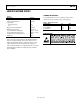
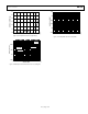
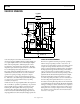
Figure 2. Pin Configuration
Table 4. Pin Function Descriptions
Pin No. Mnemonic Description
1 C
C
Coupling Capacitor. If dc coupling is desired at Pin 2, connect a coupling capacitor to this pin. If the coupling at
Pin 2 is ac, connect this pin to ground. Note that this pin is also an input, with an input impedance of 8 kΩ.
Such an input is useful for applications with high input voltages and low supply voltages.
2 V
IN
High Input Impedance Pin.
3 C
F
Connect an Auxiliary Low-Pass Filter Capacitor from the Output.
4 −V
S
Negative Supply Voltage if Dual Supplies Are Used, or Ground if Connected to a Single-Supply Source.
5 C
AV
Connect the Averaging Capacitor Here.
6 OUTPUT DC Output Voltage.
7
+V
S
Positive Supply Voltage.
8 COM Common.