
Datasheet


Data Sheet AD737
Rev. I | Page 3 of 24
SPECIFICATIONS
T
A
= 25°C, ±V
S
= ±5 V except as noted, C
AV
= 33 µF, C
C
= 10 µF, f = 1 kHz, sine wave input applied to Pin 2, unless otherwise specified.
Specifications shown in boldface are tested on all production units at final electrical test. Results from these tests are used to calculate
outgoing quality levels.
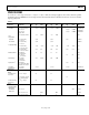
Table 1.
Parameter
Test Conditions/
Comments
AD737A, AD737J AD737K AD737J-5
Unit Min Typ Max Min Typ Max Min Typ Max
ACCURACY
Total Error E
IN
= 0 to 200 mV rms 0.2/0.3
0.4/0.5
0.2/0.2
0.2/0.3
±mV/±POR
1
±V
S
= ±2.5 V 0.2/0.3
0.4/0.5
±mV/±POR
1
±V
S
= ±2.5 V,
input to Pin 1
0.2/0.3
0.4/0.5
±mV/±POR
1
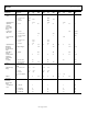
E
IN
= 200 mV to 1 V rms −1.2
±2.0
−1.2
±2.0
POR
Over
Temperature
JN, JR, KR
E
IN
= 200 mV rms,
±V
S
= ±2.5 V
0.007
0.007
0.02
±POR/°C
AN and AR
E
IN
= 200 mV rms,
±V
S
= ±2.5 V
0.014 0.014 ±POR/°C
vs. Supply Voltage
E
IN
= 200 mV rms,
±V
S
= ±2.5 V to ±5 V
0
−0.18
−0.3 0
−0.18
−0.3 0
−0.18
−0.3
%/V
E
IN
= 200 mV rms,
±V
S
= ±5 V to ±16.5 V
0
0.06
0.1 0
0.06
0.1 0
0.06
0.1
%/V
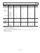
DC Reversal Error
DC-coupled,
V
IN
= 600 mV dc
1.3 2.5 1.3 2.5 POR
±V
S
= ±2.5 V
V
IN
= 200 mV dc
1.7 2.5 POR
Nonlinearity
2
E
IN
= 0 mV to
200 mV rms,
@ 100 mV rms
0
0.25
0.35 0
0.25
0.35
POR
Input to Pin 1
3
AC coupled,
E
IN
= 100 mV rms, after
correction, ±V
S
= ±2.5 V
0.02 0.1 POR
Total Error,
External Trim
E
IN
= 0 mV to
200 mV rms
0.1/0.2 0.1/0.2 0.1/0.2 ±mV/±POR
ADDITIONAL
CREST FACTOR
ERROR
4
For Crest Factors
from 1 to 3
C
AV
= C
F
= 100 µF 0.7 0.7 %
C
AV
= 22 µF, C
F
= 100 µF,
±V
S
= ±2.5 V, input to
Pin 1
1.7 %
For Crest Factors
from 3 to 5
C
AV
= C
F
= 100 µF 2.5 2.5 %
INPUT
CHARACTERISTICS
High-Z Input (Pin 2)
Signal Range
Continuous
RMS Level
±V
S
= +2.5 V
200
mV rms
±V
S
= +2.8 V/−3.2 V
200
200
mV rms
±V
S
= ±5 V to ±16.5 V
1
1
V rms