
Datasheet


AD780 Data Sheet
Rev. F | Page 10 of 12
00841-021
+V
IN
AD780
AD7884
V
OUT
V
REF
+ F
6
V
REF
+ S
2.5V/3.0V
SELECT
8
GND
4
2
1F
5V
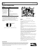
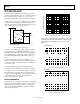
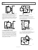
Figure 21. Precision 3 V Reference for the AD7884 16-Bit, High Speed ADC
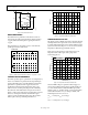
The AD780 is also ideal for use with higher resolution
converters, such as the AD7710/AD7711/AD7712 (see Figure
22. While these parts are specified with a 2.5 V internal
reference, the AD780 in 3 V mode can be used to improve the
absolute accuracy, temperature stability, and dynamic range. It
is shown in Figure 22 with the two optional noise reduction
capacitors.
00841-022
+V
IN
AD780
AD7710
V
OUT
REF IN+
6
2.5V/3.0V
O/P SELECT
8
GND
4
3
2
1F
100nF
5V
REF IN–
100F
Figure 22. Precision 2.5 V or 3.0 V Reference for the
AD7710 High Resolution, Σ-Δ ADC
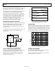
4.5 V REFERENCE FROM 5 V SUPPLY
Some 5 V high resolution ADCs can accommodate reference
voltages up to 4.5 V. The AD780 can be used to provide a
precision 4.5 V reference voltage from a 5 V supply using the
circuit shown in Figure 23. This circuit provides a regulated
4.5 V output from a supply voltage as low as 4.7 V. The high
quality tantalum 10 μF capacitor, in parallel with the ceramic
AD780 0.1 μF capacitor and the 3.9 Ω resistor, ensures a low
output impedance around 50 MHz.
00841-023
AD780
2N2907
V
OUT
5k
0.01%
4k
0.01%
2.5k
3.9
1k
0.1F
0.1F
10F
0.1F
OP90
+
–
V
SUPPLY
2
4
6
3
7
6
4
2
Figure 23. 4.5 V Reference from a Single 5 V Supply
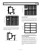
NEGATIVE (–2.5 V) REFERENCE
The AD780 can produce a negative output voltage in shunt
mode by connecting the input and output to ground, and
connecting the AD780’s GND pin to a negative supply via a bias
resistor, as shown in Figure 25.
00841-024
NC
TEMP
+V
IN
V
OUT
TRIM
GND
O/P SELECT
2.5V – NC
3.0V – GND
NC
1F
AD780
NOTES
1. I
L
= LOAD CURRENT
2. I
S
MIN = MINIMUM SHUNT CURRENT
3. NC = NO CONNECT
1
7
6
5
84
2
3
R =
V
OUT
– (V–)
I
L
+ I
S
MIN
–2.5 V
OUT
V–
Figure 24. Negative (−2.5 V Shunt Mode Reference)
A precise –2.5 V reference capable of supplying up to 100 mA to
a load can be implemented with the AD780 in series mode,
using the bootstrap circuit shown in Figure 25.
0
0841-025
AD780
2N3906
+5V
+5V
OP07
CONNECT IF
–3V OUTPUT
DESIRED
–2.5V (I
L
100mA)
–5V
–5V
OUT
1k
1000pF
+V
IN
–
+
2
4
68
Figure 25. −2.5 V High Load Current Reference