
Datasheet


AD780 Data Sheet
Rev. F | Page 6 of 12
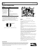
APPLYING THE AD780
The AD780 can be used without any external components to
achieve specified performance. If power is supplied to Pin 2 and
Pin 4 is grounded, Pin 6 provides a 2.5 V or 3.0 V output
depending on whether Pin 8 is left unconnected or grounded.
A bypass capacitor of 1 µF (+V
IN
to GND) should be used if the
load capacitance in the application is expected to be greater
than 1 nF. The AD780 in 2.5 V mode typically draws 700 µA of
I
q
at 5 V. This increases by ~2 µA/V up to 36 V.
00841-005
NC
TEMP
+V
IN
R
NULL
V
OUT
TRIM
GND
O/P SELECT
2.5V
–
NC
3.0V –
GND
NC
R POT
1µF
AD780
NC = NO CONNECT
1
7
6
5
8
4
2
3
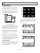
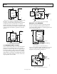
Figure 5. Optional Fine-Trim Circuit
Initial error can be nulled using a single 25 kΩ potentiometer
connected between V
OUT
, TRIM, and GND. This is a coarse
trim with an adjustment range of 4%, and is only included here
for compatibility purposes with other references. A fine trim
can be implemented by inserting a large value resistor (e.g., 1
MΩ to
5 MΩ) in series with the wiper of the potentiometer (see
Figure 5). The trim range, expressed as a fraction of the output,
is simply greater than or equal to 2.1 kΩ/R
NULL
for either the
2.5 V or 3.0 V mode.
The external null resistor affects the overall temperature
coefficient by a factor equal to the percentage of V
OUT
nulled.
For example, a 1 mV (0.03%) shift in the output caused by the
trim circuit, with a 100 ppm/°C null resistor, adds less than
0.06 ppm/°C to the output drift (0.03% × 200 ppm/°C, since the
resistors internal to the AD780 also have temperature
coefficients of less than 100 ppm/°C).
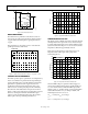
NOISE PERFORMANCE
The impressive noise performance of the AD780 can be further
improved, if desired, by adding two capacitors: a load capacitor
(C1) between the output and ground, and a compensation
capacitor (C2) between the TEMP pin and ground. Suitable
values are shown in Figure 6.
100
10
1
0.1
0.1 1 10 100
00841-006
LOAD CAPACITOR, C1 (µF)
COMPENSATION CAPACITOR, C2 (nF)
Figure 6. Compensation and Load Capacitor Combinations
C1 and C2 also improve the settling performance of the AD780
when subjected to load transients. The improvement in noise
performance is shown in Figure 7, Figure 8, Figure 9, and
Figure 10.
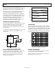
00841-007
0.1 TO 10Hz
AMPLIFIER GAIN = 100
1s100µV
100
90
10
0%
Figure 7. Standalone Noise Performance
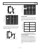
00841-008
10Hz TO 10kHz
NO AMPLIFIER
10ms20µV
100
90
10
0%
Figure 8. Standalone Noise Performance