
Datasheet

AD780
REV. B
–5–
NOISE PERFORMANCE
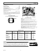
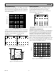
The impressive noise performance of the AD780 can be further
improved if desired by the addition of two capacitors: a load ca-
pacitor C1 between the output and ground, and a compensation
capacitor C2 between the TEMP pin and ground. Suitable val-
ues are shown in Figure 3.
100
1
0.1
0.1 1 10010
10
LOAD CAPACITOR, C1 – F
COMPENSATION CAP, C2 – nF
Figure 3. Compensation and Load Capacitor Combinations
C1 and C2 also improve the settling performance of the AD780
when subjected to load transients. The improvement in noise
performance is shown in Figures 4, 5 and 6 following.
10
90
100
0%
100
V1s
0.1 TO
10Hz
AMPLIFIER GAIN = 100
10
90
100
0%
20
V
10ms
10Hz
TO 10kHz
NO AMPLIFIER
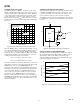
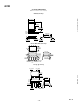
Figure 4. Stand-Alone Noise Performance
NC
TEMP
+V
IN
V
OUT
TRIM
GND
O/P SELECT
2.5V – NC
3.0V – GND
NC
AD780
NC = NO CONNECT
C2
1F
C1
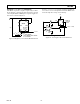
Figure 5. Noise Reduction Circuit
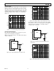
NOISE COMPARISON
The wideband noise performance of the AD780 can also be ex-
pressed in ppm. The typical performance with C1, C2 is
0.6 ppm and without external capacitors is 1.2 ppm.
This performance is respectively 7⫻ and 3⫻ lower than the
specified performance of the LT1019.
10
90
100
0%
20
V
10ms
10Hz TO 10kHz
NO AMPLIFIER
Figure 6. Reduced Noise Performance with C1 = 100
µ
F,
C2 = 100 nF
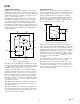
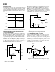
TEMPERATURE PERFORMANCE
The AD780 provides superior performance over temperature by
means of a combination of patented circuit design techniques,
precision thin film resistors and drift trimming. Temperature
performance is specified in terms of ppm/°C, but because of
nonlinearity in the temperature characteristic, the Box-Test
method is used to test and specify the part. The nonlinearity
takes the form of the characteristic S-shaped curve shown in
Figure 7. The Box-Test method forms a rectangular box around
this curve, enclosing the maximum and minimum output volt-
ages over the specified temperature range. The specified drift is
equal to the slope of the diagonal of this box.
2.0
–0.8
140
0.4
–0.4
–40
0
–60
1.6
0.8
1.2
12010080604020
0
–20
TEMPERATURE –
C
ERROR – mV
Figure 7. Typical AD780BN Temperature Drift