
Datasheet

AD7993/AD7994
Rev. 0 | Page 7 of 32
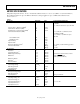
I
2
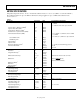
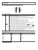
C TIMING SPECIFICATIONS
Guaranteed by initial characterization. All values measured with input filtering enabled. C
B
refers to capacitive load on the bus line.
tr and tf measured between 0.3 V
DD
and 0.7 V
DD
.
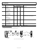
High speed mode timing specifications apply to the AD7993-1/AD7994-1 only. Standard and fast mode timing specifications apply to
both the AD7993-0/AD7994-0 and the AD7993-1/AD7994-1. See Figure 2.
Unless otherwise noted, V
DD
= 2.7 V to 5.5 V; REF
IN
= 2.5 V; T
A
=T
MIN
to T
MAX
.
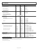
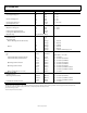
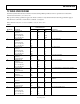
Table 3.
AD7993/AD7994
Limit at T
MIN
, T
MAX
Parameter Conditions Min Max Unit Description
f
SCL
Standard mode 100 kHz Serial clock frequency
Fast mode 400 kHz
High speed mode
C
B
= 100 pF max 3.4 MHz
C
B
= 400 pF max 1.7 MHz
t
1
Standard mode 4 µs t
HIGH
, SCL high time
Fast mode 0.6 µs
High speed mode
C
B
= 100 pF max 60 ns
C
B
= 400 pF max 120 ns
t
2
Standard mode 4.7 µs t
LOW
, SCL low time
Fast mode 1.3 µs
High speed mode
C
B
= 100 pF max 160 ns
C
B
= 400 pF max 320 ns
t
3
Standard mode 250 ns t
SU;DAT
, data setup time
Fast mode 100 ns
High speed mode 10 ns
t
4
1
Standard mode 0 3.45 µs t
HD;DAT
, data hold time
Fast mode 0 0.9 µs
High speed mode
C
B
= 100 pF max 0 70
2
ns
C
B
= 400 pF max 0 150 ns
t
5
Standard mode 4.7 µs t
SU;STA
, setup time for a repeated start condition
Fast mode 0.6 µs
High speed mode 160 ns
t
6
Standard mode 4 µs t
HD;STA
, hold time (repeated) start condition
Fast mode 0.6 µs
High speed mode 160 ns
t
7
Standard mode 4.7 µs
t
BUF
, bus free time between a stop and a start
condition
Fast mode 1.3 µs
t
8
Standard mode 4 µs t
SU;STO
, setup time for stop condition
Fast mode 0.6 µs
High speed mode 160 ns
t
9
Standard mode 1000 ns t
RDA
, rise time of SDA signal
Fast mode 20 + 0.1 C
B
300 ns
High speed mode
C
B
= 100 pF max 10 80 ns
C
B
= 400 pF max 20 160 ns