
Datasheet

AD8016 Data Sheet
Rev. C | Page 6 of 20
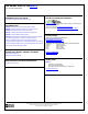
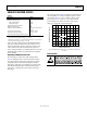
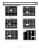
PIN CONFIGURATIONS AND FUNCTION DESCRIPTIONS
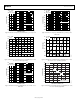
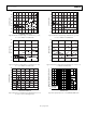
Figure 4. 24-Lead SOIC_W_BAT (RB-24) Figure 5. 28-Lead TSSOP_EP (RE-28-1)
Table 5. Pin Function Descriptions
Pin No.
Mnemonic Description SOIC_W_BAT TSSOP_EP
1 8 +V1 Positive Power Supply, Amp 1.
2 9 V
OUT
1 Output Signal, Amp 1.
3 V
INN
1 Negative Input Signal, Amp 1.
4 V
INP
1 Positive Input Signal, Amp1.
5 to 8, 17 to 20 AGND Analog Ground.
9 18 PWDN0 Power-Down Input 0.
10 20 DGND Digital Ground.
11 21 −V1 Negative Power Supply, Amp1.
12, 13
1 to 3, 12 to 17, 19,
25 to 28
NC This pin is not connected internally (see Figure 4 and Figure 5).
14 22 −V2 −V Power Supply, Amp 2.
15 23 BIAS Quiescent Current Adjust.
16 24 PWDN1 Power-Down Input 1.
21 V
INP
2 Positive Input Signal, Amp 2.
22 V
INN
2 Negative Input Signal, Amp 2.
23 6 V
OUT
2 Output Signal, Amp 2.
24 7 +V2 Positive Power Supply, Amp 2.
4 +V
IN
2 Positive Input Signal, Amp 2.
5 −V
IN
2 Negative Input Signal, Amp 2.
10 −V
IN
1 Negative Input Signal, Amp 1.
11 +V
IN
1 Positive Input Signal, Amp 1.
EP EPAD Exposed Pad. The exposed paddle is floating, not electrically connected internally.
+–
+–
+V1 +V2
1
2
3
4
24
23
22
21
5
6
7
8
9 16
10 15
11 14
12 13
NC = NO CONNECT
AD8016
TOP VIEW
(Not to Scale)
20
19
18
17
01019-002
V
OUT
1
V
INN
1
V
INP
1
AGND
AGND
AGND
AGND
PWDN0
DGND
–V1
NC
V
OUT
2
V
INN
2
V
INP
2
AGND
AGND
AGND
AGND
PWDN1
BIAS
–V2
NC
1
2
3
4
5
6
7
8
9
10
11
12
13
14
28
27
26
25
24
23
22
21
20
19
18
17
16
15
AD8016ARE
BIAS
–V2
PWDN1
NOTES
1. THE EXPOSED PADDLE IS FLOATING,
NOT ELECTRICALLY CONNECTED
INTERNALLY.
2. NC = NO CONNECT.
DGND
–V1
PWDN0
NC NC
NC
NC
NC
NC
NC
NC
NC
NC
NC
+V
IN
2
–V
IN
2
V
OUT
2
+V2
+V1
V
OUT
1
–V
IN
1
+V
IN
1
NC
NC
NC
TOP VIEW
(Not to Scale)
01019-003