
Datasheet

REV. A
AD8110/AD8111
–19–
Measuring Crosstalk
Crosstalk is measured by applying a signal to one or more channels
and measuring the relative strength of that signal on a desired
selected channel. The measurement is usually expressed as dB
down from the magnitude of the test signal. The crosstalk is
expressed by:
XT Asel s Atest s=
() ()
()
20
10
log /
where s = jw is the Laplace transform variable, Asel(s) is the
amplitude of the crosstalk-induced signal in the selected channel
and Atest(s) is the amplitude of the test signal. It can be seen
that crosstalk is a function of frequency, but not a function of
the magnitude of the test signal (to first order). In addition, the
crosstalk signal will have a phase relative to the test signal asso-
ciated with it.
A network analyzer is most commonly used to measure crosstalk
over a frequency range of interest. It can provide both magni-
tude and phase information about the crosstalk signal.
As a crosspoint system or device grows larger, the number of
theoretical crosstalk combinations and permutations can become
extremely large. For example, in the case of the 16 ⫻ 8 matrix of
the AD8110/AD8111, we can examine the number of crosstalk
terms that can be considered for a single channel, say IN00 input.
IN00 is programmed to connect to one of the AD8110/AD8111
outputs where the measurement can be made.
We can first measure the crosstalk terms associated with driving
a test signal into each of the other 15 inputs one at a time. We
can then measure the crosstalk terms associated with driving a
parallel test signal into all 15 other inputs taken two at a time in
all possible combinations; and then three at a time, etc., until,
finally, there is only one way to drive a test signal into all 15
other inputs.
Each of these cases is legitimately different from the others and
might yield a unique value depending on the resolution of the
measurement system, but it is hardly practical to measure all
these terms and then to specify them. In addition, this describes
the crosstalk matrix for just one input channel. A similar
crosstalk matrix can be proposed for every other input. In addition,
if the possible combinations and permutations for connecting
inputs to the other (not used for measurement) outputs are
taken into consideration, the numbers rather quickly grow to
astronomical proportions. If a larger crosspoint array of multiple
AD8110/AD8111s is constructed, the numbers grow larger still.
Obviously, some subset of all these cases must be selected to be
used as a guide for a practical measure of crosstalk. One common
method is to measure “all hostile” crosstalk. Su˘s term means
that the crosstalk to the selected channel is measured, while all
other system channels are driven in parallel. In general, this will
yield the worst crosstalk number, but this is not always the case
due to the vector nature of the crosstalk signal.
Other useful crosstalk measurements are those created by one
nearest neighbor or by the two nearest neighbors on either side.
These crosstalk measurements will generally be higher than
those of more distant channels, so they can serve as a worst-case
measure for any other one-channel or two-channel crosstalk
measurements.
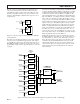
Input and Output Crosstalk
The flexible programming capability of the AD8110/AD8111
can be used to diagnose whether crosstalk is occurring more on
the input side or the output side. Some examples are illustrative.
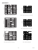
A given input channel (IN07 in the middle for this example) can
be programmed to drive OUT03. The input to IN07 is just
terminated to ground (via 50 or 75 Ω) and no signal is applied.
All the other inputs are driven in parallel with the same test
signal (practically provided by a distribution amplifier), with all
other outputs except OUT03 disabled. Since grounded IN07 is
programmed to drive OUT03, there should be no signal present.
Any signal that is present can be attributed to the other 15 hostile
input signals, because no other outputs are driven. (They are all
disabled.) Thus, this method measures the all-hostile input
contribution to crosstalk into IN07. Of course, the method
can be used for other input channels and combinations of
hostile inputs.
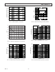
For output crosstalk measurement, a single input channel (IN00
for example) is driven and all outputs other than a given output
(IN03 in the middle) are programmed to connect to IN00.
OUT03 is programmed to connect to IN15 (far away from
IN00), which is terminated to ground. Thus OUT03 should not
have a signal present since it is listening to a quiet input. Any
signal measured at the OUT03 can be attributed to the output
crosstalk of the other seven hostile outputs. Again, this method
can be modified to measure other channels and other crosspoint
matrix combinations.
Effect of Impedances on Crosstalk
The input side crosstalk can be influenced by the output
impedance of the sources that drive the inputs. The lower the
impedance of the drive source, the lower the magnitude of the
crosstalk. The dominant crosstalk mechanism on the input side
is capacitive coupling. The high impedance inputs do not have
significant current flow to create magnetically induced crosstalk.
However, significant current can flow through the input termi-
nation resistors and the loops that drive them. Thus, the PC board
on the input side can contribute to magnetically coupled crosstalk.
From a circuit standpoint, the input crosstalk mechanism looks
like a capacitor coupling to a resistive load. For low frequencies
the magnitude of the crosstalk will be given by:
XT R C s
SM
=
()
×
[]
20
10
log
where R
S
is the source resistance, C
M
is the mutual capacitance
between the test signal circuit and the selected circuit, and s is
the Laplace transform variable.
From the equation it can be observed that this crosstalk mechanism
has a high-pass nature; it can also be minimized by reducing the
coupling capacitance of the input circuits and lowering the output
impedance of the drivers. If the input is driven from a 75 Ω terminated
cable, the input crosstalk can be reduced by buffering this signal with
a low output impedance buffer.
On the output side, the crosstalk can be reduced by driving a
lighter load. Although the AD8110/AD8111 is specified with
excellent differential gain and phase when driving a standard
150 Ω video load, the crosstalk will be higher than the minimum
obtainable due to the high output currents. These currents will
induce crosstalk via the mutual inductance of the output pins
and bond wires of the AD8110/AD8111.