
Datasheet


AD8112
Rev. 0 | Page 10 of 28
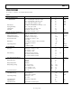
Pin No. Mnemonic Description
21, 22, 26, 30, 34, 38, 55 AV
CC
5 V for Inputs and Switch Matrix.
54 AV
CC
xx
5 V for Output Amplifier. This pin is shared by Channel Numbers xx and yy.
Must be connected.
50, 46, 42 AV
CC
xx/yy
1
5 V for Output Amplifier. This pin is shared by Channel Numbers xx and yy.
Must be connected.
52, 48, 44, 40 AV
EE
xx/yy
1
−5 V for Output Amplifier. This pin is shared by Channel Numbers xx and yy.
Must be connected.
84 A0 Parallel Data Input, TTL-compatible (Output Select LSB).
83 A1 Parallel Data Input, TTL-compatible (Output Select).
82 A2 Parallel Data Input, TTL-compatible (Output Select).
80 D0 Parallel Data Input, TTL-compatible (Input Select LSB).
79 D1 Parallel Data Input, TTL-compatible (Input Select).
78 D2 Parallel Data Input, TTL-compatible (Input Select).
77 D3 Parallel Data Input, TTL-compatible (Input Select MSB).
76 D4 Parallel Data Input, TTL-compatible (Output Enable).
23, 25, 27, 29, 31, 33, 35, 37, 85 to 93 NC No Connect.
1
xx = Chanel numbers 00 through 15 for analog inputs; yy = channel numbers 00 through 07 for analog outputs.