
Datasheet


AD9523 Data Sheet
Rev. C | Page 36 of 60
To ensure that the data transfer has completed correctly, verify
that the EEPROM data error bit (Bit 0 in Register 0xB01) is set
to 0. A value of 1 in this bit indicates a data transfer error.
PROGRAMMING THE EEPROM BUFFER SEGMENT
The EEPROM buffer segment is a register space that allows the
user to specify which groups of registers are stored to the EEPROM
during EEPROM programming. Normally, this segment does not
need to be programmed by the user. Instead, the default power-up
values for the EEPROM buffer segment allow the user to store
all of the register values from Register 0x000 to Register 0x234
to the EEPROM.
For example, if the user wants to load only the output driver set-
tings from the EEPROM without disturbing the PLL register
settings currently stored in the EEPROM, the EEPROM buffer
segment can be modified to include only the registers that apply
to the output drivers and exclude the registers that apply to the
PLL configuration.
There are two parts to the EEPROM buffer segment: register
section definition groups and operational codes. Each register
section definition group contains the starting address and
number of bytes to be written to the EEPROM.
If the AD9523 register map were continuous from Address 0x000
to Address 0x234, only one register section definition group
would consist of a starting address of 0x000 and a length of
563 bytes. However, this is not the case. The AD9523 register
map is noncontiguous, and the EEPROM is only 512 bytes long.
Therefore, the register section definition group tells the EEPROM
controller how the AD9523 register map is segmented.
There are three operational codes: IO_Update, end-of-data, and
pseudo-end-of-data. It is important that the EEPROM buffer
segment always have either an end-of-data or a pseudo-end-of-
data operational code and that an IO_Update operation code
appear at least once before the end-of-data operational code.
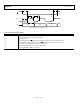
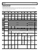
Register Section Definition Group
The register section definition group is used to define a continuous
register section for the EEPROM profile. It consists of three bytes.
The first byte defines how many continuous register bytes are in
this group. If the user puts 0x000 in the first byte, it means there
is only one byte in this group. If the user puts 0x001, it means
there are two bytes in this group. The maximum number of
registers in one group is 128.
The next two bytes are the high byte and low byte of the
memory address (16 bits) of the first register in this group.
IO_Update (Operational Code 0x80)
The EEPROM controller uses this operational code to generate
an IO_Update signal to update the active control register bank
from the buffer register bank during the download process.
At a minimum, there should be at least one IO_Update
operational code after the end of the final register section definition
group. This is needed so that at least one IO_Update occurs after
all of the AD9523 registers are loaded when the EEPROM is read.
If this operational code is absent during a write to the EEPROM,
the register values loaded from the EEPROM are not transferred
to the active register space, and these values do not take effect
after they are loaded from the EEPROM to the AD9523.
End-of-Data (Operational Code 0xFF)
The EEPROM controller uses this operational code to terminate
the data transfer process between EEPROM and the control
register during the upload and download process. The last item
appearing in the EEPROM buffer segment should be either this
operational code or the pseudo-end-of-data operational code.
Pseudo-End-of-Data (Operational Code 0xFE)
The AD9523 EEPROM buffer segment has 23 bytes that can
contain up to seven register section definition groups. If users
want to define more than seven register section definition groups,
the pseudo-end-of-data operational code can be used. During
the upload process, when the EEPROM controller receives the
pseudo-end-of-data operational code, it halts the data transfer
process, clears the REG2EEPROM bit (Bit 0, Register 0xB03),
and enables the AD9523 serial port. Users can then program
the EEPROM buffer segment again and reinitiate the data
transfer process by setting the REG2EEPROM bit to 1 and the
IO_Update bit (Bit 0, Register 0x234) to 1. The internal I²C master
then begins writing to the EEPROM, starting from the EEPROM
address held from the last writing.
This sequence enables more discrete instructions to be written
to the EEPROM than would otherwise be possible due to the
limited size of the EEPROM buffer segment. It also permits the
user to write to the same register multiple times with a different
value each time.