
Datasheet


Table Of Contents
- FEATURES
- APPLICATIONS
- FUNCTIONAL BLOCK DIAGRAM
- PRODUCT HIGHLIGHTS
- TABLE OF CONTENTS
- REVISION HISTORY
- GENERAL DESCRIPTION
- SPECIFICATIONS
- ADC DC SPECIFICATIONS—AD9640ABCPZ-80, AD9640BCPZ80, AD9640ABCPZ-105, AND AD9640BCPZ-105
- ADC DC SPECIFICATIONS—AD9640ABCPZ-125, AD9640BCPZ125, AD9640ABCPZ-150, AND AD9640BCPZ150
- ADC AC SPECIFICATIONS—AD9640ABCPZ-80, AD9640BCPZ80, AD9640ABCPZ-105, AND AD9640BCPZ-105
- ADC AC SPECIFICATIONS—AD9640ABCPZ-125, AD9640BCPZ125, AD9640ABCPZ-150, AND AD9640BCPZ 150
- DIGITAL SPECIFICATIONS
- SWITCHING SPECIFICATIONS—AD9640ABCPZ-80, AD9640BCPZ-80, AD9640ABCPZ-105, AND AD9640BCPZ105
- SWITCHING SPECIFICATIONS—AD9640ABCPZ-125, AD9640BCPZ-125, AD9640ABCPZ-150, AND AD9640BCPZ150
- TIMING SPECIFICATIONS
- ABSOLUTE MAXIMUM RATINGS
- PIN CONFIGURATIONS AND FUNCTION DESCRIPTIONS
- EQUIVALENT CIRCUITS
- TYPICAL PERFORMANCE CHARACTERISTICS
- THEORY OF OPERATION
- ADC OVERRANGE AND GAIN CONTROL
- SIGNAL MONITOR
- BUILT-IN SELF-TEST (BIST) AND OUTPUT TEST
- CHANNEL/CHIP SYNCHRONIZATION
- SERIAL PORT INTERFACE (SPI)
- MEMORY MAP
- READING THE MEMORY MAP TABLE
- EXTERNAL MEMORY MAP
- MEMORY MAP REGISTER DESCRIPTION
- Sync Control (Register 0x100)
- Fast Detect Control (Register 0x104)
- Fine Upper Threshold (Register 0x106 and Register 0x107)
- Fine Lower Threshold (Register 0x108 and Register 0x109)
- Signal Monitor DC Correction Control (Register 0x10C)
- Signal Monitor DC Value Channel A (Register 0x10D and Register 0x10E)
- Signal Monitor DC Value Channel B (Register 0x10F and Register 0x110)
- Signal Monitor SPORT Control (Register 0x111)
- Signal Monitor Control (Register 0x112)
- Signal Monitor Period (Register 0x113 to Register 0x115)
- Signal Monitor Result Channel A (Register 0x116 to Register 0x118)
- Signal Monitor Result Channel B (Register 0x119 to Register 0x11B)
- APPLICATIONS INFORMATION
- OUTLINE DIMENSIONS
AD9640
Rev. B | Page 36 of 52
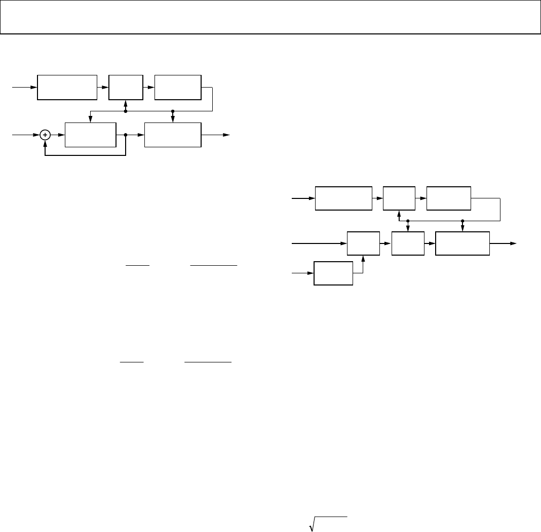
Figure 69 illustrates the rms magnitude monitoring logic.
SIGNAL MONITOR
HOLDING
REGISTER (SMR)
ACCUMULATOR
TO
MEMORY
MAP/SPORT
FROM
MEMORY
MAP
FROM
INPUT
PORTS
LOAD
CLEAR LOAD
IS COUNT = 1?
DOWN
COUNTER
SIGNAL MONITOR
PERIOD REGISTER
06547-092
Figure 69. ADC Input RMS Magnitude Monitoring Block Diagram
For rms magnitude mode, the value in the signal monitor result
(SMR) register is a 20-bit fixed-point number. The following
equation can be used to determine the rms magnitude in dBFS
from the MAG value in the register. Note that if the signal monitor
period (SMP) is a power of 2, the second term in the equation
becomes 0.
RMS Magnitude = 20 log
[]
⎥
⎦
⎤
⎢
⎣
⎡
−
⎟
⎠
⎞
⎜
⎝
⎛
)(log
20
2
2
log10
2
SMPceil
SMPMAG
For ms magnitude mode, the value in the SMR is a 20-bit fixed-
point number. The following equation can be used to determine
the ms magnitude in dBFS from the MAG value in the register.
Note that if the SMP is a power of 2, the second term in the
equation becomes 0.
MS Magnitude = 10 log
[]
⎥
⎦
⎤
⎢
⎣
⎡
−
⎟
⎠
⎞
⎜
⎝
⎛
)(log
20
2
2
log10
2
SMPceil
SMPMAG
THRESHOLD CROSSING MODE
In the threshold crossing mode of operation, the magnitude of
the input port signal is monitored over a programmable time
period (given by the SMPR) to count the number of times it
crosses a certain programmable threshold value. This mode is set
by programming Logic 1x (where x is a don’t care bit) in the
signal monitor mode bits of the signal monitor control register
or by setting the threshold crossing output enable bit in the
signal monitor SPORT control register. Before activating this
mode, the user needs to program the 24-bit SMPR and the
13-bit upper threshold register for each individual input port.
The same upper threshold register is used for both signal moni-
toring and gain control (see the ADC Overrange and Gain
Control section).
After entering this mode, the value in the SMPR is loaded into
a monitor period timer, and the countdown is started. The magni-
tude of the input signal is compared with the upper threshold
register (programmed previously) on each input clock cycle.
If the input signal has a magnitude greater than the upper
threshold register, the internal count register is incremented by 1.
The initial value of the internal count register is set to 0. This
comparison and incrementing of the internal count register
continues until the monitor period timer reaches a count of 1.
When the monitor period timer reaches a count of 1, the value
in the internal count register is transferred to the signal monitor
holding register, which can be read through the SPI port or output
through the SPORT serial port.
The monitor period timer is reloaded with the value in the SMPR
register, and the countdown is restarted. The internal count
register is also cleared to a value of 0. Figure 70 illustrates the
threshold crossing logic. The value in the SMR register is the
number of samples that have a magnitude greater than the
threshold register.
SIGNAL MONITOR
HOLDING
REGISTER (SMR)
COMPARE
A>B
UPPER
THRESHOLD
REGISTER
COMPARE
A>B
TO
MEMORY
MAP/SPORT
FROM
MEMORY
MAP
FROM
MEMORY
MAP
FROM
INPUT
PORTS
LOAD
CLEAR
LOAD
IS COUNT = 1?
DOWN
COUNTER
SIGNAL MONITOR
PERIOD REGISTER
B
A
06547-046
Figure 70. ADC Input Threshold Crossing Block Diagram
ADDITIONAL CONTROL BITS
For additional flexibility in the signal monitoring process, two
control bits are provided in the signal monitor control register.
They are the signal monitor enable bit and the complex power
calculation mode enable bit.
Signal Monitor Enable Bit
The signal monitor enable bit, Bit 0 of Register 0x112, enables
operation of the signal monitor block. If the signal monitor
function is not needed in a particular application, this bit should
be cleared (default) to conserve power.
Complex Power Calculation Mode Enable Bit
When this bit is set, the part assumes that Channel A is digitizing
the I data and Channel B is digitizing the Q data for a complex
input signal (or vice versa). In this mode, the power reported is
equal to the following:
22
QI +
This result is presented in the Signal Monitor DC Value Channel A
register if the signal monitor mode bits are set to 00. The Signal
Monitor DC Value Channel B register continues to compute the
Channel B value.
DC CORRECTION
Because the dc offset of the ADC may be significantly larger
than the signal being measured, a dc correction circuit is included
to null the dc offset before measuring the power. The dc correction
circuit can also be switched into the main signal path, but this
may not be appropriate if the ADC is digitizing a time-varying
signal with significant dc content, such as GSM.