
Datasheet


ADE5166/ADE5169/ADE5566/ADE5569 Data Sheet
Rev. D | Page 10 of 156
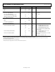
Parameter Min Typ Max Unit Test Conditions/Comments
POWER SUPPLY INPUTS
V
DD
3.13 3.3 3.46 V
V
BAT
2.4 3.3 3.7 V
INTERNAL POWER SUPPLY SWITCH (V
SWOUT
)
V
BAT
to V
SWOUT
On Resistance 12 Ω V
BAT
= 2.4 V
V
DD
to V
SWOUT
On Resistance 9 Ω V
DD
= 3.13 V
V
BAT
to/from V
DD
Switching Open Time 40 ns
BCTRL State Change and Switch Delay 18 µs
V
SWOUT
Output Current Drive 6 mA
POWER SUPPLY OUTPUTS
V
INTA
2.3
2.70
V
V
INTD
2.3 2.70 V
V
INTA
Power Supply Rejection 60 dB
V
INTD
Power Supply Rejection 50 dB
POWER SUPPLY CURRENTS
Current in Normal Mode (PSM0) 4.4 5.3 mA f
CORE
= 4.096 MHz, LCD and meter active
2.2 mA f
CORE
= 1.024 MHz, LCD and meter active
1.6 mA f
CORE
= 32.768 kHz, LCD and meter active
3 3.9 mA f
CORE
= 4.096 MHz; metering ADC and DSP,
powered down
Current in Battery Mode (PSM1) 3.3 5.05 mA f
CORE
= 4.096 MHz, LCD active, V
BAT
= 3.7 V
1 mA f
CORE
= 1.024 MHz, LCD active
Current in Sleep Mode (PSM2) 38 µA LCD active with charge pump at 3.3 V + RTC,
V
BAT
= 3.3 V
1.7 µA RTC only, T
A
= 25°C, V
BAT
= 3.3 V
1
Specifications guaranteed by design.
2
Endurance is qualified as per JEDEC Standard 22 Method A117 and measured at −40°C, +25°C, +85°C, and +125°C.
3
Retention lifetime equivalent at junction temperature (T
J
) = 85°C as per JEDEC Standard 22 Method A117. Retention lifetime derates with junction temperature.
4
Recommended crystal specifications.
5
Test carried out with all the I/Os set to a low output level.
6
Delay between power supply valid and execution of first instruction by 8052 core.