
Datasheet


ADE5166/ADE5169/ADE5566/ADE5569 Data Sheet
Rev. D | Page 8 of 156
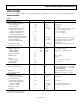
ANALOG PERIPHERALS
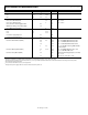
Table 3.
Parameter Min Typ Max Unit Test Conditions/Comments
INTERNAL ADCs (BATTERY, TEMPERATURE, V
DCIN
)
Power Supply Operating Range 2.4 3.7 V Measured on V
SWOUT
No Missing Codes
1
8 Bits
Conversion Delay
2
38 µs
ADC Gain
V
DCIN
Measurement 15.3 mV/LSB
V
BAT
Measurement 14.6 mV/LSB
Temperature Measurement 0.83 °C/LSB
ADC Offset
V
DCIN
Measurement at 3 V 200 LSB
V
BAT
Measurement at 3.7 V 246 LSB
Temperature Measurement at 25°C 123 LSB
V
DCIN
Analog Input
Maximum Signal Levels 0 3.3 V
Input Impedance (DC) 1 MΩ
Low V
DCIN
Detection Threshold 1.09 1.2 1.27 V
POWER-ON RESET (POR)
V
DD
POR
Detection Threshold 2.5 2.95 V
POR Active Timeout Period 33 ms
V
SWOUT
POR
Detection Threshold 1.8 2.2 V
POR Active Timeout Period 20 ms
V
INTD
POR
Detection Threshold 2.0 2.25 V
POR Active Timeout Period 16 ms
V
INTA
POR
Detection Threshold 2.0 2.25 V
POR Active Timeout Period 120 ms
BATTERY SWITCHOVER
Voltage Operating Range (V
SWOUT
) 2.4 3.7 V
V
DD
to V
BAT
Switching
Switching Threshold (V
DD
) 2.5 2.95 V
Switching Delay 10 ns When V
DD
to V
BAT
switch is activated by V
DD
30 ms When V
DD
to V
BAT
switch is activated by V
DCIN
V
BAT
to V
DD
Switching
Switching Threshold (V
DD
) 2.5 2.95 V
Switching Delay 30 ms Based on V
DD
> 2.75 V
V
SWOUT
to V
BAT
Leakage Current 10 nA V
BAT
= 0 V, V
SWOUT
= 3.43 V, T
A
= 25°C
LCD, CHARGE PUMP ACTIVE
Charge Pump Capacitance Between
LCDVP1 and LCDVP2
100 nF
LCDVA, LCDVB, LCDVC Decoupling Capacitance
470
nF
LCDVA 0 1.9 V
LCDVB 0 3.8 V 1/3 bias mode
LCDVC 0 5.8 V 1/3 bias mode
V1 Segment Line Voltage LCDVA − 0.1 LCDVA V Current on segment line = −2 µA
V2 Segment Line Voltage LCDVB − 0.1 LCDVB V Current on segment line = −2 µA
V3 Segment Line Voltage LCDVC − 0.1 LCDVC V Current on segment line = −2 µA
DC Voltage Across Segment and COMx Pin 50 mV LCDVC − LCDVB, LCDVC − LCDVA, or
LCDVB − LCDVA