
Datasheet

ADE7854/ADE7858/ADE7868/ADE7878 Data Sheet
Rev. G | Page 10 of 100
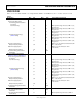
Parameter
1, 2
Min Typ Max Unit Test Conditions/Comments
MEAN ABSOLUTE VALUE (MAV)
MEASUREMENT (ADE7868 AND
ADE7878)
I mav Measurement Bandwidth (PSM1
Mode)
260 Hz
I mav Measurement Error (PSM1 Mode) 0.5 % Over a dynamic range of 100 to 1, PGA = 1, 2, 4, 8
ANALOG INPUTS
Maximum Signal Levels
±500
mV peak
PGA = 1, differential inputs between the
following pins: IAP and IAN, IBP and IBN, ICP
and ICN; single-ended inputs between the
following pins: VAP and VN, VBP and VN, VCP,
and VN
Input Impedance (DC)
IAP, IAN, IBP, IBN, ICP, ICN, VAP, VBP,
and VCP Pins
400 kΩ
VN Pin 130 kΩ
ADC Offset −24 mV
PGA = 1, uncalibrated error, see the Terminology
section
Gain Error
±4
%
External 1.2 V reference
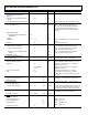
WAVEFORM SAMPLING Sampling CLKIN/2048, 16.384 MHz/2048 = 8 kSPS
Current and Voltage Channels See the Waveform Sampling Mode section
Signal-to-Noise Ratio, SNR
74
dB
PGA = 1, fundamental frequency: 45 Hz to
65 Hz, see the Terminology section
Signal-to-Noise-and-Distortion Ratio,
SINAD
74 dB
PGA = 1; fundamental frequency: 45 Hz to
65 Hz, see the Terminology section
Bandwidth (−3 dB) 2 kHz
TIME INTERVAL BETWEEN PHASES
Measurement Error 0.3 Degrees Line frequency = 45 Hz to 65 Hz, HPF on
CF1, CF2, CF3 PULSE OUTPUTS
Maximum Output Frequency 8 kHz WTHR = VARTHR = VATHR = PMAX = 33,516,139
Duty Cycle 50 %
If CF1, CF2, or CF3 frequency > 6.25 Hz and
CFDEN is even and > 1
(1 + 1/CFDEN)
× 50%
If CF1, CF2, or CF3 frequency > 6.25 Hz and
CFDEN is odd and > 1
Active Low Pulse Width 80 ms If CF1, CF2, or CF3 frequency < 6.25 Hz
Jitter 0.04 %
For CF1, CF2, or CF3 frequency = 1 Hz and
nominal phase currents are larger than 10% of
full scale
REFERENCE INPUT
REF
IN/OUT
Input Voltage Range 1.1 1.3 V Minimum = 1.2 V − 8%; maximum = 1.2 V + 8%
Input Capacitance 10 pF
ON-CHIP REFERENCE Nominal 1.2 V at the REF
IN/OUT
pin at T
A
= 25°C
PSM0 and PSM1 Modes
Temperature Coefficient −50 ±5 +50 ppm/°C
Drift across the entire temperature range of −40°C
to +85°C is calculated with reference to 25°C;
see the Reference Circuit section for more details
CLKIN
All specifications CLKIN of 16.384 MHz. See the
Crystal Circuit section for more details.
Input Clock Frequency 16.22 16.384 16.55 MHz
LOGIC INPUTS—MOSI/SDA, SCLK/SCL, SS,
RESET, PM0, AND PM1
Input High Voltage, V
INH
2.0 V VDD = 3.3 V ± 10%
Input Low Voltage, V
INL
0.8 V VDD = 3.3 V ± 10%
Input Current, I
IN
−8.7 µA Input = 0 V, VDD = 3.3 V
3 μA Input = VDD = 3.3 V
Input Capacitance, C
IN
10 pF