
Datasheet


ADM1069
Rev. C | Page 3 of 32
Supply margining can be performed with a minimum of external
components. The margining loop can be used for in-circuit
testing of a board during production (for example, to verify
board functionality at −5% of nominal supplies), or it can be
used dynamically to accurately control the output voltage of
a dc-to-dc converter.
The device also provides up to eight programmable inputs for
monitoring undervoltage faults, overvoltage faults, or out-of-
window faults on up to eight supplies. In addition, there are eight
programmable outputs that can be used as logic enables. Six of
these programmable outputs can also provide up to a 12 V output
for driving the gate of an N-FET that can be placed in the path
of a supply.
The logical core of the device is a sequencing engine (SE). This
state machine-based construction provides up to 63 different states.
This design enables very flexible sequencing of the outputs, based
on the condition of the inputs.
The ADM1069 is controlled via configuration data that can be
programmed into an EEPROM. The entire configuration can
be programmed using an intuitive GUI-based software package
provided by Analog Devices, Inc.
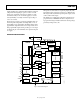
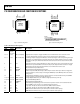
DETAILED BLOCK DIAGRAM
04735-002
GPI SIGNAL
CONDITIONING
SFD
GPI SIGNAL
CONDITIONING
SFD
SFD
SFD
SELECTABLE
ATTENUATOR
SELECTABLE
ATTENUATOR
DEVICE
CONTROLLER
OSC
EEPROM
SDA SCL A1 A0
SMBus
INTERFACE
REFOUTREFIN REFGND
VREF
12-BIT
SAR ADC
ADM1069
CONFIGURABLE
OUTPUT DRIVER
(HV)
PDO1
PDO2
PDOGND
PDO3
VCCPGND
PDO4
PDO5
CONFIGURABLE
OUTPUT DRIVER
(HV)
PDO6
CONFIGURABLE
OUTPUT DRIVER
(LV)
PDO7
CONFIGURABLE
OUTPUT DRIVER
(LV)
PDO8
SEQUENCING
ENGINE
VX2
VX3
VP2
VP3
VH
VP1
VX1
AGND
VX4
VDD
ARBITRATOR
REG 5.25V
CHARGE PUMP
DAC1
V
OUT
DAC
DAC4
V
OUT
DAC
DAC2
DAC3
VDDCAP
Figure 2. Detailed Block Diagram