
Datasheet


ADM1069
Rev. C | Page 5 of 32
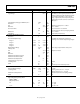
Parameter Min Typ Max Unit Test Conditions/Comments
ANALOG-TO-DIGITAL CONVERTER
Signal Range 0 V
REFIN
V
The ADC can convert signals presented to the
VH, VPx, and VXx pins; VPx and VH input signals
are attenuated depending on the selected
range; a signal at the pin corresponding to the
selected range is from 0.573 V to 1.375 V at the
ADC input
Input Reference Voltage on REFIN Pin, V
REFIN
2.048 V
Resolution 12 Bits
INL ±2.5 LSB Endpoint corrected, V
REFIN
= 2.048 V
Gain Error ±0.05 % V
REFIN
= 2.048 V
Conversion Time 0.44 ms One conversion on one channel
84 ms All eight channels selected, averaging enabled
Offset Error ±2 LSB V
REFIN
= 2.048 V
Input Noise 0.25 LSB
rms
Direct input (no attenuator)
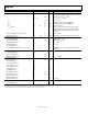
BUFFERED VOLTAGE OUTPUT DACs
Resolution 8 Bits
Code 0x80 Output Voltage
Four DACs are individually selectable for
centering on one of four output voltage ranges
Range 1 0.592 0.6 0.603 V
Range 2 0.796 0.8 0.803 V
Range 3 0.996 1 1.003 V
Range 4 1.246 1.25 1.253 V
Output Voltage Range 601.25 mV Same range, independent of center point
LSB Step Size 2.36 mV
INL ±0.75 LSB Endpoint corrected
DNL ±0.4 LSB
Gain Error 1 %
Maximum Load Current (Source) 100 μA
Maximum Load Current (Sink) 100 μA
Maximum Load Capacitance 50 pF
Settling Time into 50 pF Load 2 μs
Load Regulation 2.5 mV Per mA
PSRR 60 dB DC
40 dB 100 mV step in 20 ns with 50 pF load
REFERENCE OUTPUT
Reference Output Voltage 2.043 2.048 2.053 V No load
Load Regulation −0.25 mV Sourcing current, I
DACxMAX
= −100 μA
+0.25 mV Sinking current, I
DACxMAX
= +100 μA
Minimum Load Capacitance 1 μF Capacitor required for decoupling, stability
PSRR 60 dB DC
PROGRAMMABLE DRIVER OUTPUTS
High Voltage (Charge Pump) Mode
(PDO1 to PDO6)
Output Impedance 500 kΩ
V
OH
11 12.5 14 V I
OH
= 0 μA
10.5 12 13.5 V I
OH
= 1 μA
I
OUTAVG
20 μA 2 V < V
OH
< 7 V