
Datasheet


Data Sheet ADM1171
Rev. A | Page 13 of 16
gate voltage of the external FET. This minimizes the bus supply
voltage drop caused by the fault and protects neighboring cards.
As the voltage across the sense resistor approaches the current
limit, a timer activates. This timer resets again if the sense
voltage returns below this level. If the sense voltage is any
voltage below 44 mV, the timer is guaranteed to be off. Should
the current continue to increase, the ADM1171 tries to regulate
the gate of the FET to achieve a limit of 50 mV across the sense
resistor. However, if the device is unable to regulate the fault
current and the sense voltage further increases, a larger pull-
down, in the order of milliamperes, is enabled to compensate
for fast current surges. If the sense voltage is any voltage greater
than 56 mV, this pull-down is guaranteed to be on. When the
timer expires, the GATE pin shuts down.
TIMER FUNCTION
The TIMER pin is responsible for several key functions on the
ADM1171. A capacitor controls the initial power on reset time
and the amount of time an overcurrent condition lasts before
the FET shuts down. On theADM1171-1, the timer pin also
controls the time between auto retry pulses. There are pull-up
and pull-down currents internally available to control the timer
functions. The voltage on the TIMER pin is compared with two
threshold voltages: COMP1 (0.2 V) and COMP2 (1.3 V). The
four timing currents are listed in Table 5.
Table 5.
Timing Current Level (μA)
Pull-up 5
Pull-up 60
Pull-down 2
Pull-down 100
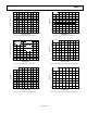
POWER-UP TIMING CYCLE
The ADM1171 is in reset when the ON (ON-
CLR
) pin is held
low. The GATE pin is pulled low and the TIMER pin is pulled
low with a 100 μA pull-down. At Time Point 2 in Figure 36, the
ON (ON-
CLR
) pin is pulled high. For the device to startup
correctly, the supply voltage must be above UVLO, the ON
(ON-
CLR
) pin must be above 1.3 V, and the TIMER pin voltage
must be less than 0.2 V. The initial timing cycle begins when these
three conditions are met, and the TIMER pin is pulled high with
5 μA. At Time Point 3, the TIMER reaches the COMP2 threshold.
This is the end of the first section of the initial cycle. The 100 μA
current source then pulls down the TIMER pin until it reaches
0.2 V at Time Point 4. The initial cycle delay (Time Point 2 to
Time Point 4) relates to C
TIMER
by equation
t
INITIAL
= 1.3 × C
TIMER
/5 μA (4)
When the initial cycle ends, a start-up cycle activates and the
GATE pin is pulled high; the TIMER pin continues to pull down.
1
2
NORMAL
CYCLE
INITIAL
CYCLE
START-UP
CYCLE
RESET
MODE
3
4
V
IN
V
ON
V
TIMER
V
GATE
V
OUT
05125-002
Figure 36. Power-Up Timing
2µA
5µA
60µA
100µA
V
IN
V
ON
V
TIMER
V
GATE
V
OUT
I
RSENSE
NORMAL
CYCLE
INITIAL
CYCLE
START-UP
CYCLE
RESET
MODE
05125-003
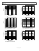
Figure 37. Power-Up into Capacitor
CIRCUIT BREAKER TIMING CYCLE
When the voltage across the sense resistor exceeds the circuit
breaker trip voltage, the 60 μA timer pull-up current is activated.
If the sense voltage falls below this level before the TIMER pin
reaches 1.3 V, the 60 μA pull-up is disabled and the 2 μA pull-
down is enabled. This is likely to happen if the overcurrent fault
is only transient, such as an inrush current. This is shown in
Figure 37. However, if the overcurrent condition is continuous
and the sense voltage remains above the circuit breaker trip
voltage, the 60 μA pull-up remains active. This allows the TIMER
pin to reach the high trip point of 1.3 V and initiate the GATE
shutdown. On the ADM1171-2, the TIMER pin continues pulling
up but switches to the 5 μA pull-up when it reaches the 1.3 V