
Datasheet


ADM2682E/ADM2687E
Rev. 0 | Page 17 of 24
is assumed to be unpowered or nonfunctional, in which case,
the isolator output is forced to a default state by the watchdog
timer circuit.
This situation should occur in the ADM2682E/ADM2687E devices
only during power-up and power-down operations. The limitation
on the ADM2682E/ADM2687E magnetic field immunity is set
by the condition in which induced voltage in the transformer
receiving coil is sufficiently large to either falsely set or reset the
decoder. The following analysis defines the conditions under
which this can occur.
The 3.3 V operating condition of the ADM2682E/ADM2687E
is examined because it represents the most susceptible mode of
operation. The pulses at the transformer output have an amplitude
of >1.0 V. The decoder has a sensing threshold of about 0.5 V,
thus establishing a 0.5 V margin in which induced voltages can
be tolerated. The voltage induced across the receiving coil is
given by
V = (−dβ/dt)Σπr
n
2
; n = 1, 2, … , N
where:
β is magnetic flux density (gauss).
N is the number of turns in the receiving coil.
r
n
is the radius of the n
th
turn in the receiving coil (cm).
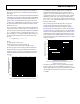
Given the geometry of the receiving coil in the ADM2682E/
ADM2687E and an imposed requirement that the induced
voltage be, at most, 50% of the 0.5 V margin at the decoder, a
maximum allowable magnetic field is calculated as shown in
Figure 39.
MAGNETIC FIELD FREQUENCY (Hz)
100
MAXIMUM ALLOWABLE MAGNETIC FLUX
DENSITY (kgauss)
0.001
1M
10
0.01
1k 10k 10M
0.1
1
100M100k
09927-019
Figure 39. Maximum Allowable External Magnetic Flux Density
For example, at a magnetic field frequency of 1 MHz, the
maximum allowable magnetic field of 0.2 kgauss induces a
voltage of 0.25 V at the receiving coil. This is about 50% of the
sensing threshold and does not cause a faulty output transition.
Similarly, if such an event occurs during a transmitted pulse
(and is of the worst-case polarity), it reduces the received pulse
from >1.0 V to 0.75 V, which is still well above the 0.5 V sensing
threshold of the decoder.
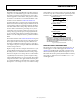
The preceding magnetic flux density values correspond to
specific current magnitudes at given distances from the
ADM2682E/ADM2687E transformers. Figure 40 expresses
these allowable current magnitudes as a function of frequency
for selected distances. As shown in Figure 40, the ADM2682E/
ADM2687E are extremely immune and can be affected only by
extremely large currents operated at high frequency very close
to the component. For the 1 MHz example, a 0.5 kA current must
be placed 5 mm away from the ADM2682E/ADM2687E to affect
component operation.
MAGNETIC FIELD FREQUENCY (Hz)
MAXIMUM ALLOWABLE CURRENT (kA)
1k
100
10
1
0.1
0.01
1k 10k 100M100k 1M 10M
DISTANCE = 5mm
DISTANCE = 1m
DISTANCE = 100mm
09927-020
Figure 40. Maximum Allowable Current for Various Current-to-
ADM2682E/ADM2687E Spacings
Note that in combinations of strong magnetic field and high
frequency, any loops formed by PCB traces can induce error
voltages sufficiently large to trigger the thresholds of succeeding
circuitry. Take care in the layout of such traces to avoid this
possibility.