
Datasheet

Data Sheet ADM6305/ADM6306
Rev. A | Page 5 of 12
PIN CONFIGURATIONS AND FUNCTION DESCRIPTIONS
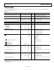
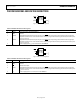
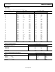
Figure 3. ADM6305 Pin Configuration
Table 4. ADM6305 Pin Function Descriptions
Pin No. Mnemonic Description
1
RESET
Active Low, Open-Drain
RESET
Output.
2 GND Ground.
3 RST IN1 Adjustable Reset Comparator Input. This pin asserts
RESET
if the input voltage is below threshold. Its high input
impedance allows the use of an external resistor divider to program the monitoring threshold. Connect this pin to
V
CC
if it is not used.
4 RST IN2 Adjustable Reset Comparator Input. This pin asserts
RESET
if the input voltage is below threshold. Its high input
impedance allows the use of an external
resistor divider to program the monitoring threshold. Connect this pin to
V
CC
if it is not used.
5 V
CC
Power Supply Input. V
CC
is not monitored on the ADM6305.
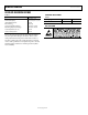
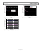
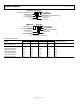
Figure 4. ADM6306 Pin Configuration
Table 5. ADM6306 Pin Function Descriptions
Pin No. Mnemonic Description
1
RESET
Active Low, Open-Drain
RESET
Output.
2 GND Ground.
3
MR
Manual Reset Input.
4 RST IN Adjustable Reset Comparator Input. This pin asserts
RESET
if the input voltage is below threshold. Its high input
impedance allows the use of an
external resistor divider to program the monitoring threshold. Connect this pin to
V
CC
if it is not used.
5 V
CC
Power Supply Input. V
CC
is monitored on the ADM6306.
RESET
1
RST IN1
3
GND
2
V
CC
5
RST IN2
3
ADM6305
TOP VIEW
(Not to Scale)
09345-003
RESET
1
MR
3
GND
2
V
CC
5
RST IN
3
ADM6306
TOP VIEW
(Not to Scale)
09345-004