
Datasheet

ADM6316/ADM6317/ADM6318/ADM6319/ADM6320/ADM6321/ADM6322 Data Sheet
Rev. F | Page 10 of 16
APPLICATIONS INFORMATION
WATCHDOG INPUT CURRENT
To minimize watchdog input current (and minimize overall
power consumption), leave WDI low for the majority of the
watchdog timeout period. When driven high, WDI can draw
as much as 160 µA. Pulsing WDI low-to-high-to-low at a low
duty cycle reduces the effect of the large input current. When
WDI is unconnected, a window comparator disconnects the
watchdog timer from the reset output circuitry so that reset is
not asserted when the watchdog timer times out.
NEGATIVE-GOING V
CC
TRANSIENTS
To avoid unnecessary resets caused by fast power supply transients,
the ADM6316/ADM6317/ADM6318/ADM6319/ADM6320/
ADM6321/ADM6322 are equipped with glitch rejection circuitry.
The typical performance characteristic in Figure 14 plots V
CC
transient duration vs. the transient magnitude. The curves show
combinations of transient magnitude and duration for which a
reset is not generated for 4.63 V and 2.93 V reset threshold
parts. For example, with the 2.93 V threshold, a transient that
goes 100 mV below the threshold and lasts 8 µs typically does
not cause a reset, but if the transient is any larger in magnitude
or duration, a reset is generated. An optional 0.1 µF bypass
capacitor mounted close to V
CC
provides additional glitch
rejection.
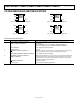
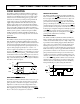
ENSURING RESET VALID TO V
CC
= 0 V
Both active-low and active-high reset outputs are guaranteed
to be valid for V
CC
as low as 1 V. However, by using an external
resistor with push-pull configured reset outputs, valid outputs
for V
CC
as low as 0 V are possible. For an active-low reset output, a
resistor connected between
RESET
and ground pulls the output
low when it is unable to sink current. For the active-high case, a
resistor connected between RESET and V
CC
pulls the output high
when it is unable to source current. A large resistance, such as
100 kΩ, should be used so that it does not overload the reset
output when V
CC
is above 1 V.
ADM6316/
ADM6318/
ADM6319
V
CC
RESET
100kΩ
ADM6317/
ADM6318/
ADM6319/
ADM6321/
ADM6322
V
CC
RESET
100kΩ
04533-018
Figure 19. Ensuring Reset Valid to V
CC
= 0 V
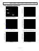
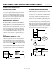
WATCHDOG SOFTWARE CONSIDERATIONS
In implementing the microprocessor’s watchdog strobe code,
quickly switching WDI low to high and then high to low (mini-
mizing WDI high time) is desirable for current consumption
reasons. However, a more effective way of using the watchdog
function can be considered.
A low-to-high-to-low WDI pulse within a given subroutine
prevents the watchdog from timing out. However, if the sub-
routine becomes stuck in an infinite loop, the watchdog cannot
detect this because the subroutine continues to toggle WDI. A
more effective coding scheme for detecting this error involves
using a slightly longer watchdog timeout. In the program that
calls the subroutine, WDI is set high. The subroutine sets WDI
low when it is called. If the program executes without error, WDI
is toggled high and low with every loop of the program. If the
subroutine enters an infinite loop, WDI is kept low, the watchdog
times out, and the microprocessor is reset (see Figure 20).
START
SET WD
I
HIGH
PROGRAM
C
ODE
SUBROUTINE
SET WDI
LOW
RETUR
N
INFINITE LOOP:
WATCHDO
G
T
IMES OUT
R
ESET
04533-021
Figure 20. Watchdog Flow Diagram
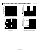
RESET RESET
WDI I/OMR
ADM6316
V
CC
MICROPROCESSOR
04533-020
Figure 21. Typical Application Circuit