
Datasheet
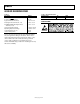

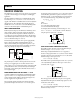
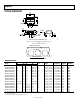
Table Of Contents

ADM6339
Rev. A | Page 5 of 12
PIN CONFIGURATION AND FUNCTION DESCRIPTIONS
IN
1
1
IN
2
2
IN
3
3
6
GND
5
IN
4
4
ADM6339
TOP VIEW
(Not to Scale)
08169-002
RESET
Figure 2. Pin Configuration
Table 4. Pin Function Descriptions
Pin No. Mnemonic Description
1 IN
1
Monitored Input Voltage 1.
2 IN
2
Monitored Input Voltage 2. IN
2
is the power supply input for the ADM6339.
3 IN
3
Monitored Input Voltage 3.
4 IN
4
Monitored Input Voltage 4.
5 GND Ground.
6
RESET
Active Low RESET Output. RESET goes low when an input drops below the specified threshold (or above in the
case of the −0.5 V and −5.0 V input options). After all inputs rise above the threshold voltage, RESET
remains low
for 200 ms (typical) before going high. RESET
is open drain with a weak internal pull-up to IN
2
, typically 10 μA.