
Datasheet
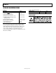

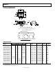
Table Of Contents

ADM6339
Rev. A | Page 8 of 12
THEORY OF OPERATION
The ADM6339 is a compact, low power supervisory circuit that
is capable of monitoring up to four voltages in a multisupply
application.
The device includes several factory-set voltage threshold options
f o r m on i t o r i n g − 5 . 0 V, + 1 . 8 V, + 2 .5 V, + 3 . 0 V, + 3 . 3 V, a n d + 5 . 0 V
supplies. The ADM6339 is available with one to three adjustable
threshold options. The adjustable voltage threshold options
available are +1.23 V, +0.62 V, and −0.5 V. See the Ordering Guide
section for a list and description of all available options.
INPUT CONFIGURATION
Built-in hysteresis improves the ADM6339’s immunity to short
input transients, without noticeably reducing the threshold
accuracy. The internal comparators each have a hysteresis of
0.3% with respect to the reset threshold voltage. (The IN
4
input
of the ADM6339Q model has a hysteresis of 0.47% with respect
to its reset threshold voltage of −0.487 V.)
Monitored inputs are resistant to short power supply glitches.
Figure 6 depicts the ADM6339 glitch immunity data. To
increase noise immunity in noisy applications, place a 0.1 F
capacitor between the IN
2
input and ground. Adding capacitance
to IN
1
, IN
3
, and IN
4
also improves noise immunity.
08169-003
IN
1
ADM6339
MONITORED
SUPPLIES
MICROPROCESSOR
IN
2
RESET
IN
3
IN
4
GND
Figure 13. Typical Applications Circuit
IN
2
must always be used for normal operation because it is the
device’s power supply input. Do not allow unused monitor
inputs to float or to be grounded. Unused IN
3
or IN
4
inputs with
positive thresholds can be connected directly to the IN
2
input.
Unused IN
4
options with negative thresholds must be tied to a
more negative supply.
MONITORING NEGATIVE VOLTAGES < −5.0 V
A number of ADM6339 models include a pretrimmed threshold
option to monitor −5.0 V voltage levels. Use a low impedance
resistor divider network similar to that shown in Figure 14 to
monitor supplies more negative than −5.0 V.
The current through the external resistor divider should be
greater than the input current for the −5.0 V monitor options.
For an input monitor current error of <1%, the resistor network
current should be greater than or equal to 2 mA (for I
IN4
= 20 µA
maximum). Set R
2
= 2.5 k. Calculate R
1
based on the desired
V
INTH
reset threshold voltage, using the following equation:
R
1
= R
2
((V
INTH
/V
TH
) − 1)
where:
R
2
≤ 2.49 k.
V
INTH
is the desired threshold voltage.
V
TH
is the internal threshold voltage.
For example, when monitoring a nominal voltage of −12 V,
V
INTH
= −11.1 V, V
TH
= −4.63 V, and R
2
= 2.49 k. Therefore,
using the previous equation, R
1
= 3.48 k.
08169-004
R
2
R
1
V
INTH
ADM6339
Figure 14. Negative Voltage Monitoring
USER ADJUSTABLE THRESHOLD OPTIONS
The ADM6339 offers the choice of three adjustable IN
x
input
threshold voltages: +1.23 V, +0.62 V, or −0.5 V.
When using an adjustable threshold of 1.23 V (typical), to
monitor a voltage greater than 1.23 V, connect a resistor divider
network to the device as shown in Figure 15. V
INTH
, the desired
threshold voltage, can be expressed as
V
INTH
= 1.23 V((R
1
+ R
2
)/(R
2
))
The ADM6339 has a guaranteed input current of ±0.1 µA on its
1.23 V adjustable input. Resistor values up to 100 k can be
used for R
2
with <1% error.
0
8169-005
V
INTH
R
1
R
2
V
REF
= 1.23V
ADM6339
Figure 15. Setting the 1.23 V Adjustable Monitor
The same approach is taken when using the 0.62 V (typical)
adjustable threshold input. Use the following equation to solve
for the values of R
1
and R
2
:
V
INTH
= 0.62 V((R
1
+ R
2
)/(R
2
))
The 0.62 V (typical) adjustable threshold input offers high
threshold accuracy of ±0.8%.