
Datasheet
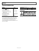

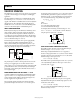
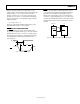
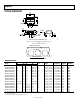
Table Of Contents

ADM6339
Rev. A | Page 9 of 12
When monitoring a voltage more negative than −0.5 V, a
scheme similar to that previously described in the Monitoring
Negative Voltages < −5.0 V section is used. For an input
monitor current error of <1%, the resistor network current
should be ≥500 µA (for I
IN4
= 5 µA maximum). Calculate R
1
based on the desired V
INTH
reset threshold voltage, using the
following equation:
R
1
= R
2
((V
INTH
/V
TH
) − 1)
where V
INTH
is the desired threshold voltage and V
TH
is the
internal threshold voltage, −0.487 V (typical).
RESET OUTPUT CONFIGURATION
The
RESET
output asserts low if a monitored INx voltage
drops below its voltage threshold (or goes above its associated
threshold in the case of the −0.5 V and −5.0 V input options).
After all voltages exceed their associated threshold level, the
reset signal remains low for the reset timeout period, t
RP
(200 ms typical).
08169-017
IN
x
RESET
V
TH
t
RD
10%
90%
t
RP
Figure 16. ADM6339
RESET
Timing
RESET
is open drain with a weak internal pull-up to IN
2
of
10 A (typical). Many applications that interface with other
logic devices do not require an external pull-up resistor.
However, if an external pull-up resistor is required and it is
connected to a voltage ranging from 0 V to 5.5 V, the resistor
overdrives the internal pull-up. Reverse current flow from the
external pull-up voltage to IN
2
is prevented by the internal
circuitry.
08169-006
ADM6339
RESET
100kΩ
RESET
V
CC
5
V
IN
2
= 3.3
V
Figure 17. Interfacing with a Different Logic Supply Voltage