
Datasheet


ADM690–ADM695
REV. A
–10–
+APPLICATION INFORMATION
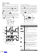
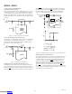
Increasing the Drive Current
If the continuous output current requirements at V
OUT
exceed
100 mA or if a lower V
CC
–V
OUT
voltage differential is desired,
an external PNP pass transistor may be connected in parallel
with the internal transistor. The BATT ON output (ADM691/
ADM693/ADM695) can directly drive the base of the external
transistor.
V
OUT
V
CC
BATTERY
+5V
INPUT
POWER
0.1µF0.1µF
BATT
ON
V
BATT
PNP TRANSISTOR
ADM691
ADM693
ADM695
Figure 17. Increasing the Drive Current
Using a Rechargeable Battery for Back Up
If a capacitor or a rechargeable battery is used for back up then
the charging resistor should be connected to V
OUT
since this
eliminates the discharge path that would exist during power
down if the resistor is connected to V
CC
.
V
OUT
V
CC
RECHARGEABLE
BATTERY
+5V
INPUT
POWER
0.1µF
0.1µF
V
BATT
ADM69x
R
I =
V
OUT
– V
BATT
R
Figure 18. Rechargeable Battery
Adding Hysteresis to the Power Fail Comparator
For increased noise immunity, hysteresis may be added to the
power fail comparator. Since the comparator circuit is nonin-
verting, hysteresis can be added simply by connecting a resistor be-
tween the
PFO output and the PFI input as shown in Figure 19.
When
PFO is low, resistor R
3
sinks current from the summing
junction at the PFI pin. When
PFO is high, the series combina-
tion of R
3
and R
4
source current into the PFI summing junc-
tion. This results in differing trip levels for the comparator.
ADM69x
R
2
1.3V
PFO
R
1
7805
R
4
R
3
+7V TO +15V
INPUT
POWER
+5V
PFI
V
CC
TO
µP NMI
5V
0V
0V
V
L
V
H
V
IN
PFO
V
H
= 1.3V
(
1+ ––– + –––
)
V
L
= 1.3V
(
1+ ––– – –––––––––––––
)
ASSUMING R
4
< <
R
3
THEN
HYSTERESIS V
H
– V
L
= 5V
(
–––
)
R
1
R
2
R
1
R
3
R
1
R
2
R
1
R
2
R
1
(5V – 1.3V)
1.3V (R
3 +
R
4
)
Figure 19. Adding Hysteresis to the Power Fail Comparator
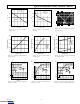
Monitoring the Status of the Battery
The power fail comparator can be used to monitor the status of
the backup battery instead of the power supply if desired. This
is shown in Figure 20. The PFI input samples the battery volt-
age and generates an active low
PFO signal when the battery
voltage drops below a chosen threshold. It may be necessary to
apply a test load in order to determine the loaded battery volt-
age. This can be done under processor control using
CE
OUT.
Since CE
OUT
is forced high during the battery backup mode, the
test load will not be applied to the battery while it is in use, even
if the microprocessor is not powered.
Downloaded from Arrow.com.Downloaded from Arrow.com.Downloaded from Arrow.com.Downloaded from Arrow.com.Downloaded from Arrow.com.Downloaded from Arrow.com.Downloaded from Arrow.com.Downloaded from Arrow.com.Downloaded from Arrow.com.Downloaded from Arrow.com.