
Datasheet


Microprocessor Supervisory
Circuit in 4-Lead SOT-143 with DSP
Data Sheet
ADM811/ADM812
Rev. G Document Feedback
Information furnished by Analog Devices is believed to be accurate and reliable. However, no
responsibility is assumed by Analog Devices for its use, nor for any infringements of patents or other
rights of third parties that may result from its use. Specifications subject to change without notice. No
license is granted by implication or otherwise under any patent or patent rights of Analog Devices.
Trademarks and registered trademarks are the property of their respective owners.
One Technology Way, P.O. Box 9106, Norwood, MA 02062-9106, U.S.A.
Tel: 781.329.4700 ©2013 Analog Devices, Inc. All rights reserved.
Technical Support www.analog.com
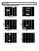
FEATURES
Superior upgrade for MAX811/MAX812
Specified over temperature
Low power consumption: 5 µA typical
Precision voltage monitor: 2.5 V, 3 V, 3.3 V, 5 V options
Reset assertion down to 1 V
CC
Power-on reset: 140 ms minimum
Logic low
RESET
output (ADM811)
Logic high RESET output (ADM812)
Built-in manual reset
APPLICATIONS
Microprocessor systems
Controllers
Intelligent instruments
Automotive systems
Safety systems
Portable instruments
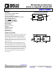
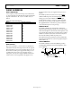
FUNCTIONAL BLOCK DIAGRAM
RESET
GENERATOR
DEBOUNCE
V
REF
RESET/RESET
GND
V
CC
MR
ADM811/ADM812
00092-001
Figure 1.
GENERAL DESCRIPTION
The ADM811/ADM812 are reliable voltage monitoring devices
suitable for use in most voltage monitoring applications. The
ADM811/ADM812 are designed to monitor six different
voltages, each allowing a 5% or 10% degradation of standard
PSU voltages before a reset occurs. These voltages have been
selected for the effective monitoring of 2.5 V, 3 V, 3.3 V, and 5 V
supply voltage levels.
Included in this circuit is a debounced manual reset input.
Reset can be activated using an electrical switch (or an input
from another digital device) or by a degradation of the supply
voltage. The manual reset function is very useful, especially if
the circuit in which the ADM811/ADM812 are operating enters
into a state that can only be detected by the user. Allowing the
user to reset a system manually can reduce the damage or
danger that could otherwise be caused by an out-of-control
or locked system.
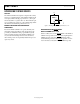
ADM811
GND
V
CC
MR RESET
MICROPROCESSOR
SYSTEM
GND
V
CC
RESET
100kΩ
00092-002
Figure 2. Typical ADM811 Operating Circuit