
Datasheet


ADP1720
Rev. A | Page 4 of 16
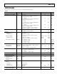
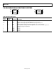
Parameter Symbol Conditions Min Typ Max Unit
POWER SUPPLY REJECTION RATIO PSRR f = 120 Hz, V
IN
= 8 V, V
OUT
= 1.6 V –90 dB
f = 1 kHz, V
IN
= 8 V, V
OUT
= 1.6 V –80 dB
f = 10 kHz, V
IN
= 8 V, V
OUT
= 1.6 V –60 dB
f = 120 Hz, V
IN
= 8 V, V
OUT
= 5 V –83 dB
f = 1 kHz, V
IN
= 8 V, V
OUT
= 5 V –70 dB
f = 10 kHz, V
IN
= 8 V, V
OUT
= 5 V –50 dB
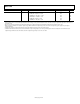
1
Accuracy when OUT is connected directly to ADJ. When OUT voltage is set by external feedback resistors, absolute accuracy in adjust mode depends on the tolerances
of resistors used.
2
Based on an end-point calculation using 1 mA and 50 mA loads. See Fi for typical load regulation performance for loads less than 1 mA. gure 6
3
Dropout voltage is defined as the input to output voltage differential when the input voltage is set to the nominal output voltage. This applies only for output
voltages above 4 V.
4
Start-up time is defined as the time between the rising edge of EN to OUT being at 95% of its nominal value.
5
Current limit threshold is defined as the current at which the output voltage drops to 90% of the specified typical value. For example, the current limit for a 5.0 V
output voltage is defined as the current that causes the output voltage to drop to 90% of 5.0 V, or 4.5 V.