
Datasheet


Table Of Contents
EVAL-ADP2118
Rev. 0 | Page 4 of 16
MEASURING EVAULATION BOARD
PERFORMANCE
Measuring the Switching Waveform
To observe the switching waveform with an oscilloscope,
place the oscilloscope probe tip at Test Point T4 with the
probe ground at GND. Set the scope to dc, 2 V/division,
and 1 µs/division time base. The switching waveform should
alternate between 0 V and approximately the input voltage.
Measuring Load Regulation
Load regulation should be tested by increasing the load at the
output and measuring the output voltage between the T3 and
T5 test points.
Measuring Line Regulation
Vary the input voltage and measure the output voltage at a fixed
output current. Input voltage can be measured between T1 and
T2. The output voltage is measured between T3 and T5.
Measuring Efficiency
The efficiency, η, is measured by comparing the input power
with the output power.
ININ
OUTOUT
IV
IV
η
×
×
=
Measuring Inductor Current
The inductor current can be measured by removing one end of
the inductor from the pad on the board and using a wire con-
nected between the pad and the inductor. Then, a current probe
can be used to measure the inductor current.
Measuring Output Voltage Ripple
To observe the output voltage ripple, place an oscilloscope
probe across the output capacitor (C4) with the probe ground
lead at the negative (−) capacitor terminal and the probe tip at
the positive (+) capacitor terminal. Set the oscilloscope to ac,
10 mV/division, 2 µs/division time base, and 20 MHz bandwidth.
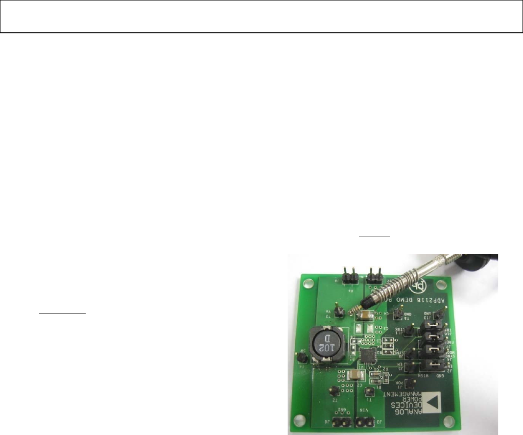
A standard oscilloscope probe has a long wire ground clip. For
high frequency measurements, this ground clip picks up high
frequency noise and injects it into the measured output ripple.
Figure 2 shows an easy way to measure the output ripple prop-
erly. It requires removing the oscilloscope probe sheath and
wrapping a nonshielded wire around the oscilloscope probe.
By keeping the ground lengths on the oscilloscope probe as
short as possible, true ripple can be measured.
Output Voltage Change
The ADP2118 evaluation board output is preset to 1.2 V;
however, the output voltage can be adjusted to other voltages
using the following equation:
+
×=
3
34
V6.0
R
RR
V
OUT
08742-002
Figure 2. Output Ripple Measurement