
Datasheet


Table Of Contents
EVAL-ADP2118
Rev. 0 | Page 7 of 16
Table 6. Cross Frequency and Phase Margin—V
OUT
= 1.8 V
C
OUT
(µF) L (µH) V
IN
3.3 V 5 V
47 1 f
C
(kHz) 103 103
PM (Degrees) 61 61
1.5 f
C
(kHz) 86 94
PM (Degrees) 47 50
2.2 f
C
(kHz) 74 82
PM (Degrees) 42 49
3.3 f
C
(kHz) 67 76
PM (Degrees) 36 41
100 1 f
C
(kHz) 63 65
PM (Degrees) 68 68
1.5 f
C
(kHz) 61 66
PM (Degrees) 54 57
2.2 f
C
(kHz) 57 63
PM (Degrees) 46 51
3.3 f
C
(kHz) 51 58
PM (Degrees) 39 45
Table 7. Cross Frequency and Phase Margin—V
OUT
= 3.3 V
C
OUT
(µF) L (µH) V
IN
3.3 V 5 V
47 1 f
C
(kHz) N/A 64
PM (Degrees) 73
1.5 f
C
(kHz) 62
PM (Degrees) 65
2.2 f
C
(kHz) 58
PM (Degrees) 55
3.3 f
C
(kHz) 53
PM (Degrees) 47
100 1 f
C
(kHz) N/A 45
PM (Degrees) 74
1.5 f
C
(kHz) 42
PM (Degrees) 70
2.2 f
C
(kHz) 40
PM (Degrees) 62
3.3 f
C
(kHz) 38
PM (Degrees) 55
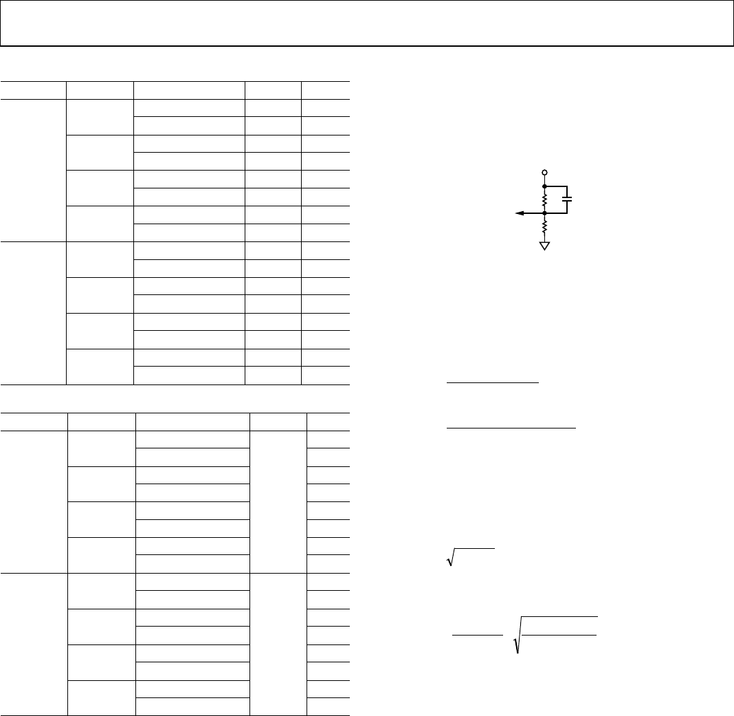
PERFORMANCE IMPROVEMENT
The ADP2118 uses internal compensation for ease-of-use but
limits optimization of the converter’s transient performance.
This section describes how to use a feedforward capacitor in the
feedback resistor divider to optimize the transient response.
R
BOT
R
TOP
C
FF
V
OUT
08742-004
Figure 4. Feedforward Capacitor Added to Resistor Divider
Figure 4 shows the feedback resistor divider with the feed-
forward capacitor. Using a feedforward capacitor allows the
regulator to be more responsive to high frequency disturbances
on the output. This capacitor introduces a zero (Equation 5)
and pole (Equation 6) in the system:
FF
TOP
Z
CR
f
××π×
=
2
1
(5)
BOTTOP
FF
BOTTOP
P
RRC
RR
f
×××π×
+
=
2
(6)
From Table 2 to Table 7, the cross frequency (f
C
) without the
feedforward capacitor is known. Using Equation 7, calculate the
required feedforward capacitor. Based on this calculated value, a
standard value can be selected to obtain the best transient
performance.
P
Z
C
fff ×=
(7)
From Equation 5, Equation 6, and Equation 7, the C
FF
value
shown in Equation 8 can be obtained.
( )
BOTTOP
BOTTOP
C
FF
RR
RR
f
C
×
+
×
×π×
=
2
2
1
(8)