
Datasheet
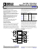


ADP5034 Data Sheet
Rev. E | Page 4 of 28
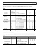
SPECIFICATIONS
GENERAL SPECIFICATIONS
V
AVIN
= V
IN1
= V
IN2
= 2.3 V to 5.5 V; V
IN3
= V
IN4
= 1.7 V to 5.5 V; T
J
= −40°C to +125°C for minimum/maximum specifications, and T
A
=
25°C for typical specifications, unless otherwise noted.
Table 2.
Parameter Symbol Test Conditions/Comments Min Typ Max Unit
INPUT VOLTAGE RANGE V
AVIN
, V
IN1
, V
IN2
2.3 5.5 V
THERMAL SHUTDOWN
Threshold TS
SD
T
J
rising 150 °C
Hysteresis TS
SD-HYS
20 °C
START-UP TIME
1
BUCK1, LDO1, LDO2 t
START1
250 µs
BUCK2 t
START2
300 µs
EN1, EN2, EN3, EN4, MODE INPUTS
Input Logic High V
IH
1.1 V
Input Logic Low V
IL
0.4 V
Input Leakage Current V
I-LEAKAGE
0.05 1 µA
INPUT CURRENT
All Channels Enabled I
STBY-NOSW
No load, no buck switching 108 175 µA
All Channels Disabled I
SHUTDOWN
T
J
= −40°C to +85°C 0.3 1 µA
VIN1 UNDERVOLTAGE LOCKOUT
High UVLO Input Voltage Rising UVLO
VIN1RISE
3.9 V
High UVLO Input Voltage Falling
UVLO
VIN 1 FALL
3.1
V
Low UVLO Input Voltage Rising UVLO
VIN1RISE
2.275 V
Low UVLO Input Voltage Falling UVLO
VIN1FA L L
1.95 V
1
Start-up time is defined as the time from EN1 = EN2 = EN3 = EN4 from 0 V to V
AVIN
to VOUT1, VOUT2, VOUT3, and VOUT4 reaching 90% of their nominal level. Start-up
times are shorter for individual channels if another channel is already enabled. See the Typical Performance Characteristics section for more information.