
Datasheet


Data Sheet ADR3525/ADR3530/ADR3533/ADR3540/ADR3550
Rev. 0 | Page 9 of 20
PIN CONFIGURATION AND FUNCTION DESCRIPTIONS
09594-002
ENABLE
1
GND SENSE
2
GND FORCE
3
NC
4
V
IN
8
V
OUT
SENSE
7
V
OUT
FORCE
6
NC
5
NOTES
1. NC = NO CONNECT. DO NOT
CONNECT TO THIS PIN.
ADR35xx
TOP VIEW
(Not to Scale)
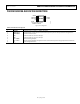
Figure 2. Pin Configuration
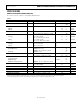
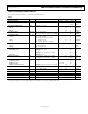
Table 9. Pin Function Descriptions
Pin No. Mnemonic Description
1 ENABLE Enable Connection. Enables or disables the device.
2 GND SENSE Ground Voltage Sense Connection. Connect directly to the point of lowest potential in the application.
3 GND FORCE Ground Force Connection.
4 NC No Connect. Do not connect to this pin.
5 NC No Connect. Do not connect to this pin.
6 V
OUT
FORCE Reference Voltage Output.
7 V
OUT
SENSE Reference Voltage Output Sensing Connection. Connect directly to the voltage input of the load devices.
8 V
IN
Input Voltage Connection.