
Datasheet


ADSP-21261/ADSP-21262/ADSP-21266
Rev. G | Page 5 of 48 | December 2012
The ADSP-2126x’s SRAM can be configured as a maximum of
64K words of 32-bit data, 128K words of 16-bit data, 42K words
of 48-bit instructions (or 40-bit data), or combinations of differ-
ent word sizes up to two megabits. All of the memory can be
accessed as 16-bit, 32-bit, 48-bit, or 64-bit words. A 16-bit float-
ing-point storage format is supported that effectively doubles
the amount of data that can be stored on-chip. Conversion
between the 32-bit floating-point and 16-bit floating-point for-
mats is performed in a single instruction. While each memory
block can store combinations of code and data, accesses are
most efficient when one block stores data using the DM bus for
transfers, and the other block stores instructions and data using
the PM bus for transfers.
Using the DM bus and PM buses, with one dedicated to each
memory block, assures single-cycle execution with two data
transfers. In this case, the instruction must be available in the
cache.
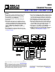
DMA Controller
The ADSP-2126x’s on-chip DMA controller allows zero-over-
head data transfers without processor intervention. The DMA
controller operates independently and invisibly to the processor
core, allowing DMA operations to occur while the core is simul-
taneously executing its program instructions. DMA transfers
can occur between the ADSP-2126x’s internal memory and its
serial ports, the SPI-compatible (serial peripheral interface)
port, the IDP (input data port), parallel data acquisition port
(PDAP), or the parallel port. Up to 22 channels of DMA are
available on the ADSP-2126x—one for the SPI interface, 12 via
the serial ports, eight via the input data port, and one via the
processor’s parallel port. Programs can be downloaded to the
ADSP-2126x using DMA transfers. Other DMA features
include interrupt generation upon completion of DMA trans-
fers, and DMA chaining for automatic linked DMA transfers.
Table 4. Internal Memory Space (ADSP-21261)
IOP Registers 0x0000 0000–0003 FFFF
Long Word (64 Bits)
Extended Precision Normal or
Instruction Word (48 Bits) Normal Word (32 Bits) Short Word (16 Bits)
Block 0 SRAM
0x0004 0000–0x0004 1FFF
Block 0 SRAM
0x0008 0000–0x0008 2AAA
Block 0 SRAM
0x0008 0000–0x0008 3FFF
Block 0 SRAM
0x0010 0000–0x0010 7FFF
Reserved
0x0004 2000–0x0005 7FFF
Reserved Reserved
0x0008 4000–0x000A FFFF
Reserved
0x0010 8000–0x0015 FFFF
Block 0 ROM
0x0005 8000–0x0005 DFFF
Block 0 ROM
0x000A 0000–0x000A 7FFF
Block 0 ROM
0x000B 0000–0x000B BFFF
Block 0 ROM
0x0016 0000–0x0017 7FFF
Reserved
0x0005 E000–0x0005 FFFF
Reserved Reserved
0x000B C000–0x000B FFFF
Reserved
0x0017 8FFF–0x0017 FFFF
Block 1 SRAM
0x0006 0000–0x0006 1FFF
Block 1 SRAM
0x000C 0000–0x000C 2AAA
Block 1 SRAM
0x000C 0000–0x000C 3FFF
Block 1 SRAM
0x0018 0000–0x0018 7FFF
Reserved
0x0006 2000–0x0007 7FFF
Reserved Reserved
0x000C 4000–0x000E FFFF
Reserved
0x0018 8000–0x001D FFFF
Block 1 ROM
0x0007 8000–0x0007 DFFF
Block 1 ROM
0x000E 0000–0x000E 7FFF
Block 1 ROM
0x000F 0000–0x000F BFFF
Block 1 ROM
0x001E 0000–0x001F 7FFF
Reserved
0x0007 E000–0x0007 FFFF
Reserved Reserved
0x000F C000–0x000F FFFF
Reserved
0x0000