
DSP Microcomputers Instructions Manual

ADSP-2181/ADSP-2183
REV. 0
–11–
These ADSP-2181/ADSP-2183 pins must be connected only to
the EZ-ICE connector in the target system. These pins have no
function except during emulation, and do not require pull-up or
pull-down resistors. The traces for these signals between the
ADSP-2181/ADSP-2183 and the connector must be kept as
short as possible, no longer that 3 inches.
The following pins are also used by the EZ-ICE:
BR
BG
RESET
GND
The EZ-ICE uses the EE (emulator enable) signal to take con-
trol of the ADSP-2181/ADSP-2183 in the target system. This
causes the processor to use its
ERESET, EBR, and EBG pins
instead of the
RESET, BR, and BG pins. The BG output is
three-stated. These signals do not need to be jumper-isolated in
your system.
The EZ-ICE connects to your target system via a ribbon cable
and a 14-pin female plug. The female plug is plugged onto the
14-pin connector (a pin strip header) on the target board.
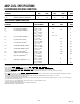
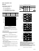
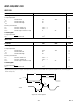
Target Board Connector for EZ-ICE Probe
The EZ-ICE connector (a standard pin strip header) is shown
in Figure 7. You must add this connector to your target board
design if you intend to use the EZ-ICE. Be sure to allow enough
room in your system to fit the EZ-ICE probe onto the 14-pin
connector.
×
12
34
56
78
910
11 12
13 14
GND
KEY (NO PIN)
RESET
BR
BG
TOP VIEW
EBG
EBR
ELOUT
EE
EINT
ELIN
ECLK
EMS
ERESET
Figure 7. Target Board Connector for EZ-ICE
The 14-pin, 2-row pin strip header is keyed at the Pin 7 loca-
tion—you must remove Pin 7 from the header. The pins must
be 0.025 inch square and at least 0.20 inch in length. Pin spac-
ing should be 0.1 × 0.1 inches. The pin strip header must have
at least 0.15 inch clearance on all sides to accept the EZ-ICE
probe plug. Pin strip headers are available from vendors such as
3M, McKenzie, and Samtec.
Target Memory Interface
For your target system to be compatible with the EZ-ICE emu-
lator, it must comply with the memory interface guidelines
listed below.
PM, DM, BM, IOM, & CM
Design your Program Memory (PM), Data Memory (DM),
Byte Memory (BM), I/O Memory (IOM), and Composite
Memory (CM) external interfaces to comply with worst case
device timing requirements and switching characteristics as
specified in the DSP’s data sheet. The performance of the
EZ-ICE may approach published worst case specification for
some memory access timing requirements and switching
characteristics.
Note: If your target does not meet the worst case chip specifi-
cation for memory access parameters, you may not be able to
emulate your circuitry at the desired CLKIN frequency. De-
pending on the severity of the specification violation, you may
have trouble manufacturing your system as DSP components
statistically vary in switching characteristic and timing require-
ments within published limits.
Restriction: All memory strobe signals on the ADSP-2181/
ADSP-2183 (
RD, WR, PMS, DMS, BMS, CMS, and IOMS)
used in your target system must have 10 kΩ pull-up resistors
connected when the EZ-ICE is being used. The pull-up resis-
tors are necessary because there are no internal pull-ups to
guarantee their state during prolonged three-state conditions
resulting from typical EZ-ICE debugging sessions. These resis-
tors may be removed at your option when the EZ-ICE is not
being used.
Target System Interface Signals
When the EZ-ICE board is installed, the performance on some
system signals change. Design your system to be compatible
with the following system interface signal changes introduced
by the EZ-ICE board:
• EZ-ICE emulation introduces an 8 ns propagation delay
between your target circuitry and the DSP on the
RESET
signal.
• EZ-ICE emulation introduces an 8 ns propagation delay be-
tween your target circuitry and the DSP on the
BR signal.
• EZ-ICE emulation ignores
RESET and BR when single-
stepping.
• EZ-ICE emulation ignores
RESET and BR when in Emula-
tor Space (DSP halted).
• EZ-ICE emulation ignores the state of target
BR in certain
modes. As a result, the target system may take control of the
DSP’s external memory bus only if bus grant (
BG) is asserted
by the EZ-ICE board’s DSP.