
Datasheet

ADSP-BF531/ADSP-BF532/ADSP-BF533
Rev. I | Page 7 of 64 | August 2013
Each event type has an associated register to hold the return
address and an associated return-from-event instruction. When
an event is triggered, the state of the processor is saved on the
supervisor stack.
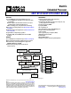
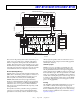
The ADSP-BF531/ADSP-BF532/ADSP-BF533 processors’ event
controller consists of two stages, the core event controller (CEC)
and the system interrupt controller (SIC). The core event con-
troller works with the system interrupt controller to prioritize
and control all system events. Conceptually, interrupts from the
peripherals enter into the SIC, and are then routed directly into
the general-purpose interrupts of the CEC.
Core Event Controller (CEC)
The CEC supports nine general-purpose interrupts (IVG15–7),
in addition to the dedicated interrupt and exception events. Of
these general-purpose interrupts, the two lowest priority inter-
rupts (IVG15–14) are recommended to be reserved for software
interrupt handlers, leaving seven prioritized interrupt inputs to
support the peripherals of the processor. Table 2 describes the
inputs to the CEC, identifies their names in the event vector
table (EVT), and lists their priorities.
System Interrupt Controller (SIC)
The system interrupt controller provides the mapping and rout-
ing of events from the many peripheral interrupt sources to the
prioritized general-purpose interrupt inputs of the CEC.
Although the processors provide a default mapping, the user
can alter the mappings and priorities of interrupt events by writ-
ing the appropriate values into the interrupt assignment
registers (SIC_IARx). Table 3 describes the inputs into the SIC
and the default mappings into the CEC.
Event Control
The processors provide a very flexible mechanism to control the
processing of events. In the CEC, three registers are used to
coordinate and control events. Each register is 32 bits wide:
• CEC interrupt latch register (ILAT) – The ILAT register
indicates when events have been latched. The appropriate
bit is set when the processor has latched the event and
cleared when the event has been accepted into the system.
This register is updated automatically by the controller, but
it can also be written to clear (cancel) latched events. This
register can be read while in supervisor mode and can only
be written while in supervisor mode when the correspond-
ing IMASK bit is cleared.
• CEC interrupt mask register (IMASK) – The IMASK regis-
ter controls the masking and unmasking of individual
events. When a bit is set in the IMASK register, that event is
unmasked and is processed by the CEC when asserted. A
cleared bit in the IMASK register masks the event,
preventing the processor from servicing the event even
though the event may be latched in the ILAT register. This
register can be read or written while in supervisor mode.
Note that general-purpose interrupts can be globally
enabled and disabled with the STI and CLI instructions,
respectively.
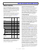
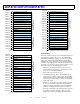
Table 2. Core Event Controller (CEC)
Priority
(0 is Highest) Event Class EVT Entry
0Emulation/Test ControlEMU
1Reset RST
2 Nonmaskable Interrupt NMI
3ExceptionEVX
4Reserved
5 Hardware Error IVHW
6 Core Timer IVTMR
7 General Interrupt 7 IVG7
8 General Interrupt 8 IVG8
9 General Interrupt 9 IVG9
10 General Interrupt 10 IVG10
11 General Interrupt 11 IVG11
12 General Interrupt 12 IVG12
13 General Interrupt 13 IVG13
14 General Interrupt 14 IVG14
15 General Interrupt 15 IVG15
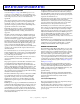
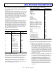
Table 3. System Interrupt Controller (SIC)
Peripheral Interrupt Event Default Mapping
PLL Wakeup IVG7
DMA Error IVG7
PPI Error IVG7
SPORT 0 Error IVG7
SPORT 1 Error IVG7
SPI Error IVG7
UART Error IVG7
Real-Time Clock IVG8
DMA Channel 0 (PPI) IVG8
DMA Channel 1 (SPORT 0 Receive) IVG9
DMA Channel 2 (SPORT 0 Transmit) IVG9
DMA Channel 3 (SPORT 1 Receive) IVG9
DMA Channel 4 (SPORT 1 Transmit) IVG9
DMA Channel 5 (SPI) IVG10
DMA Channel 6 (UART Receive) IVG10
DMA Channel 7 (UART Transmit) IVG10
Timer 0 IVG11
Timer 1 IVG11
Timer 2 IVG11
Port F GPIO Interrupt A IVG12
Port F GPIO Interrupt B IVG12
Memory DMA Stream 0 IVG13
Memory DMA Stream 1 IVG13
Software Watchdog Timer IVG13