
Datasheet
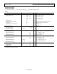
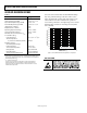
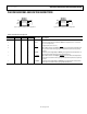

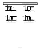

Table Of Contents

Data Sheet ADT6501/ADT6502/ADT6503/ADT6504
Rev. B | Page 5 of 16
PIN CONFIGURATIONS AND FUNCTION DESCRIPTIONS
Figure 3. ADT6501/ADT6502 Pin Configuration
Figure 4. ADT6503/ADT6504 Pin Configuration
Table 3. Pin Function Descriptions
Pin Number
ADT6501 ADT6502 ADT6503 ADT6504 Mnemonic Description
1, 2 1, 2 1, 2 1, 2 GND Ground.
3 3 3 3 HYST Hysteresis Input. Connects HYST to GND for 2°C hysteresis or connects to
V
CC
for 10°C hysteresis.
4 4 4 4 V
CC
Supply Input (2.7 V to 5.5 V).
5 — — —
TOVER
Open-Drain, Active Low Output.
TOVER
goes low when the temperature of
the part exceeds the factory-programmed threshold; must use a pull-up
resistor.
— 5 — — TOVER Push-Pull, Active High Output. TOVER goes high when the temperature of
the part exceeds the factory-programmed threshold.
— — 5 —
TUNDER
Open-Drain, Active Low Output.
TUNDER
goes low when the temperature
of the part exceeds the factory-programmed threshold; must use a pull-up
resistor.
— — — 5 TUNDER Push-Pull, Active High Output. TUNDER goes high when the temperature
of the part exceeds the factory-programmed threshold.
GND
1
GND
2
HYST
3
TOVER/
TOVER
5
V
CC
4
ADT6501/
ADT6502
TOP VIEW
(Not to Scale)
06096-003
GND
1
GND
2
HYST
3
TUNDER/
TUNDER
5
V
CC
4
ADT6503/
ADT6504
TOP VIEW
(Not to Scale)
06096-004