
Datasheet


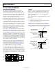
Table Of Contents

ADuM1250/ADuM1251 Data Sheet
Rev. I | Page 6 of 16
DIN V VDE V 0884-10 (VDE V 0884-10) INSULATION CHARACTERISTICS
This isolator is suitable for reinforced isolation only within the safety limit data. Maintenance of the safety data is ensured by protective
circuits. The asterisk (*) marking on the package denotes DIN V VDE V 0884-10 approval for a 560 V peak working voltage.
Table 6.
Description Test Conditions/Comments Symbol Characteristic Unit
Installation Classification per DIN VDE 0110
For Rated Mains Voltage ≤ 150 V rms I to IV
For Rated Mains Voltage ≤ 300 V rms I to III
For Rated Mains Voltage ≤ 400 V rms I to II
Climatic Classification 40/105/21
Pollution Degree per DIN VDE 0110, Table 1 2
Maximum Working Insulation Voltage V
IORM
560 V peak
Input to Output Test Voltage, Method B1
V
IORM
× 1.875 = V
PR
, 100% production test, t
m
= 1 sec,
partial discharge < 5 pC
V
PR
1050 V peak
Input to Output Test Voltage, Method A V
IORM
× 1.6 = V
PR
, t
m
= 60 sec, partial discharge < 5 pC V
PR
After Environmental Tests Subgroup 1 896 V peak
After Input and/or Safety Tests Subgroup 2
and Subgroup 3
V
IORM
× 1.2 = V
PR
, t
m
= 60 sec, partial discharge < 5 pC 672 V peak
Highest Allowable Overvoltage Transient overvoltage, t
TR
= 10 sec V
TR
4000 V peak
Safety Limiting Values
Maximum value allowed in the event of a failure
(see Figure 3)
Case Temperature T
S
150 °C
V
DD1
+ V
DD2
Current I
TMAX
212 mA
Insulation Resistance at T
S
V
IO
= 500 V R
S
>10
9
Ω
CASE TEMPERATURE (°C)
SAFETY-LIMITING CURRENT (mA)
0
0
350
50 100 150 200
50
300
150
100
200
250
06113-003
Figure 3. Thermal Derating Curve, Dependence of Safety-Limiting Values on
Case Temperature, per DIN V VDE V 0884-10
RECOMMENDED OPERATING CONDITIONS
Table 7.
Parameter Rating
Operating Temperature (T
A
)
A Grade −40°C to +105°C
S Grade −40°C to +125°C
Supply Voltages (V
DD1
, V
DD2
)
1
3.0 V to 5.5 V
Input/Output Signal Voltage
(V
SDA1
, V
SCL1
, V
SDA2
, V
SCL2
)
5.5 V
Capacitive Load
Side 1 (C
L1
) 40 pF
Side 2 (C
L2
) 400 pF
Static Output Loading
Side 1 (I
SDA1
, I
SCL1
) 0.5 mA to 3 mA
Side 2 (I
SDA2
, I
SCL2
) 0.5 mA to 30 mA
1
All voltages are relative to their respective ground. See the Magnetic Field
Immunity section for information about immunity to external magnetic
fields.