
Datasheet


Data Sheet ADuM1400/ADuM1401/ADuM1402
INSULATION LIFETIME
All insulation structures eventually break down when subjected
to voltage stress over a sufficiently long period. The rate of
insulation degradation is dependent on the characteristics of
the voltage waveform applied across the insulation. In addition
to the testing performed by the regulatory agencies, Analog
Devices carries out an extensive set of evaluations to determine
the lifetime of the insulation structure within the ADuM1400/
ADuM1401/ADuM1402.
Analog Devices performs accelerated life testing using voltage
levels higher than the rated continuous working voltage. Accel-
eration factors for several operating conditions are determined.
These factors allow calculation of the time to failure at the actual
working voltage. The values shown in Table 14 summarize the
peak voltage for 50 years of service life for a bipolar ac operating
condition and the maximum CSA/VDE approved working
voltages. In many cases, the approved working voltage is higher
than a 50-year service life voltage. Operation at these high working
voltages can lead to shortened insulation life in some cases.
The insulation lifetime of the ADuM1400/ADuM1401/
ADuM1402 depends on the voltage waveform type imposed
across the isolation barrier. The iCoupler insulation structure
degrades at different rates depending on whether the waveform
is bipolar ac, unipolar ac, or dc. Figure 21, Figure 22, and Figure 23
illustrate these different isolation voltage waveforms, respectively.
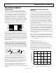
Bipolar ac voltage is the most stringent environment. The goal
of a 50-year operating lifetime under the ac bipolar condition
determines the Analog Devices recommended maximum
working voltage.
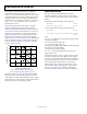
In the case of unipolar ac or dc voltage, the stress on the insulation
is significantly lower, which allows operation at higher working
voltages while still achieving a 50-year service life. The working
voltages listed in Table 14 can be applied while maintaining the
50-year minimum lifetime, provided the voltage conforms to either
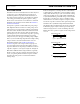
the unipolar ac or dc voltage cases. Any cross-insulation voltage
waveform that does not conform to Figure 22 or Figure 23 should
be treated as a bipolar ac waveform, and its peak voltage should
be limited to the 50-year lifetime voltage value listed in Table 14.
Note that the voltage presented in Figure 22 is shown as sinusoidal
for illustration purposes only. It is meant to represent any voltage
waveform varying between 0 V and some limiting value. The
limiting value can be positive or negative, but the voltage cannot
cross 0 V.
0V
RATED PEAK VOLTAGE
03786-021
Figure 21. Bipolar AC Waveform
0V
RATED PEAK VOLTAGE
03786-022
Figure 22. Unipolar AC Waveform
0V
RATED PEAK VOLTAGE
03786-023
Figure 23. DC Waveform
Rev. K | Page 29 of 31