
Datasheet


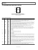

Table Of Contents

ADuM4160 Data Sheet
Rev. D | Page 8 of 16
PIN CONFIGURATION AND FUNCTION DESCRIPTIONS
V
BUS1
1
GND
1
* 2
V
DD1
3
PDEN
4
V
BUS2
16
GND
2
*15
V
DD2
14
SPD
13
SPU 5 PIN12
UD– 6 DD–11
UD+ 7 DD+10
GND
1
* 8 GND
2
*9
ADuM4160
TOP VIEW
(Not to Scale)
NC = NO CONNECT
*
PIN 2 AND PIN 8 ARE INTERNALLY CONNECTED, AND CONNECTING
BOTH TO GND
1
IS RECOMMENDED. PIN 9 AND PIN 15 ARE INTERNALLY
CONNECTED, AND CONNECTING BOTH TO GND
2
IS RECOMMENDED.
08171-003
Figure 3. Pin Configuration
Table 9. Pin Function Descriptions
Pin No. Mnemonic Direction Description
1 V
BUS1
Power
Input Power Supply for Side 1. Where the isolator is powered by the USB bus voltage, 4.5 V to 5.5 V,
connect V
BUS1
to the USB power bus. Where the isolator is powered from a 3.3 V power supply, connect
V
BUS1
to V
DD1
and to the external 3.3 V power supply. Bypass to GND
1
is required.
2 GND
1
Return Ground 1. Ground reference for Isolator Side 1.
3 V
DD1
Power
Power Supply for Side 1. Where the isolator is powered by the USB bus voltage, 4.5 V to 5.5 V, the V
DDI
pin
should be used for a bypass capacitor to GND
1
. Signal lines that may require pull up, such as PDEN and
SPU, should be tied to this pin. Where the isolator is powered from a 3.3 V power supply, connect V
BUS1
to
V
DD1
and to the external 3.3 V power supply. Bypass to GND
1
is required.
4 PDEN Input
Pull-Down Enable. This pin is read when exiting reset. For standard operation, connect this pin to V
DD1
.
When connected to GND
1
while exiting from reset, the downstream pull-down resistors are
disconnected, allowing buffer impedance measurements.
5 SPU Input
Speed Select Upstream Buffer. Active high logic input. Selects full speed slew rate, timing, and logic
conventions when SPU is high, and low speed slew rate, timing, and logic conventions when SPU is tied
low. This input must be set high via connection to V
DD1
or set low via connection to GND
1
and must
match Pin 13.
6 UD− I/O Upstream D−.
7 UD+ I/O Upstream D+.
8 GND
1
Return Ground 1. Ground reference for Isolator Side 1.
9 GND
2
Return Ground 2. Ground reference for Isolator Side 2.
10 DD+ I/O Downstream D+.
11 DD− I/O Downstream D−.
12 PIN
Input
Upstream Pull-Up Enable. PIN controls the power connection to the pull-up for the upstream port. It can
be tied to V
DD2
for operation on power-up, or tied to an external control signal for applications requiring
delayed enumeration.
13 SPD Input
Speed Select Downstream Buffer. Active high logic input. Selects full speed slew rate, timing, and logic
conventions when SPD is high, and low speed slew rate, timing, and logic conventions when SPD is tied
low. This input must be set high via connection to V
DD2
or low via connection to GND
2
, and must match
Pin 5.
14 V
DD2
Power
Power Supply for Side 2. Where the isolator is powered by the USB bus voltage, 4.5 V to 5.5 V, the V
DD2
pin
should be used for a bypass capacitor to GND
2
. Signal lines that may require pull-up, such as SPD, can be
tied to this pin. Where the isolator is powered from a 3.3 V power supply, connect V
BUS2
to V
DD2
and to the
external 3.3 V power supply. Bypass to GND
2
is required.
15 GND
2
Return Ground 2. Ground reference for Isolator Side 2.
16 V
BUS2
Power
Input Power Supply for Side 2. Where the isolator is powered by the USB bus voltage, 4.5 V to 5.5 V,
connect V
BUS2
to the USB power bus. Where the isolator is powered from a 3.3 V power supply, connect
V
BUS2
to V
DD2
and to the external 3.3 V power supply. Bypass to GND
2
is required.