
Datasheet


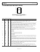

Table Of Contents

Data Sheet ADuM4160
Rev. D | Page 9 of 16
Table 10. Truth Table, Control Signals, and Power (Positive Logic)
1
V
SPU
Input
V
BUS1
, V
DD1
State
V
UD+
,
V
UD−
State
V
SPD
Input
V
BUS2
, V
DD2
State
V
DD+
,
V
DD−
State
V
PIN
Input Notes
H Powered Active H Powered Active H
Input and output logic set for full speed logic convention
and timing.
L Powered Active L Powered Active H
Input and output logic set for low speed logic convention
and timing.
L Powered Active H Powered Active H
Not allowed: V
SPU
and V
SPD
must be set to the same value.
USB host detects communications error.
H Powered Active L Powered Active H
Not allowed: V
SPU
and V
SPD
must be set to the same value.
USB host detects communications error.
X Powered Z X Powered Z L
Upstream Side 1 presents a disconnected state to the USB
cable.
X Unpowered X X Powered Z X
When power is not present on V
DD1
, the downstream data
output drivers revert to high-Z within 32 bit times. The
downstream side initializes in high-Z state.
X Powered Z X Unpowered X X
When power is not present on V
DD2
, the upstream side
disconnects the pull-up and disables the upstream drivers
within 32 bit times.
1
H represents logic high input or output, L represents logic low input or output, X represents the don’t care logic input or output, and Z represents the high impedance
output state.