
Datasheet


Data Sheet ADuM5401/ADuM5402/ADuM5403/ADuM5404
Rev. D | Page 7 of 28
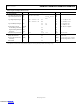
Table 9. Input and Output Characteristics
Parameter Symbol Min Typ Max Unit Test Conditions/Comments
DC SPECIFICATIONS
Logic High Input Threshold V
IH
0.7 × V
ISO
or 0.7 × V
DD1
V
Logic Low Input Threshold V
IL
0.3 × V
ISO
or 0.3 ×
V
DD1
V
Logic High Output Voltages V
OH
V
DD1
− 0.3 or V
ISO
− 0.3 3.3 V I
Ox
= −20 μA, V
Ix
= V
IxH
V
DD1
− 0.5 or V
ISO
− 0.5 3.1 V I
Ox
= −4 mA, V
Ix
= V
IxH
Logic Low Output Voltages V
OL
0.0 0.1 V I
Ox
= 20 μA, V
Ix
= V
IxL
0.0 0.4 V I
Ox
= 4 mA, V
Ix
= V
IxL
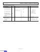
Undervoltage Lockout UVLO V
DD1
, V
DDL
, V
ISO
supplies
Positive Going Threshold V
UV+
2.7 V
Negative Going Threshold V
UV−
2.4 V
Hysteresis V
UVH
0.3 V
Input Currents per Channel I
I
−10 +0.01 +10 μA 0 V ≤ V
Ix
≤ V
DDx
AC SPECIFICATIONS
Output Rise/Fall Time t
R
/t
F
2.5 ns 10% to 90%
Common-Mode Transient
Immunity
1
|CM| 25 35 kV/μs
V
Ix
= V
DD1
or V
ISO
, V
CM
= 1000 V,
transient magnitude = 800 V
Refresh Rate f
r
1.0 Mbps
1
|CM| is the maximum common-mode voltage slew rate that can be sustained while maintaining V
O
> 0.7 × V
DD1
or 0.7 × V
ISO
for a high output or V
O
< 0.3 × V
DD1
or 0.3 × V
ISO
for a
low output. The common-mode voltage slew rates apply to both rising and falling common-mode voltage edges.
Downloaded from Arrow.com.Downloaded from Arrow.com.Downloaded from Arrow.com.Downloaded from Arrow.com.Downloaded from Arrow.com.Downloaded from Arrow.com.Downloaded from Arrow.com.