
Datasheet


ADSP-21479 EZ-Board Evaluation System Manual 1-5
Using ADSP-21479 EZ-Board
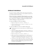
EZ-Board Installation
For correct operation, install the software in the order presented in the
VisualDSP++ Installation Quick Reference Card. Substitute instructions in
step 3 with instructions in this section.
There are two options to connect the EZ-Board hardware to a personal
computer (PC) running VisualDSP++ 5.0: via an Analog Devices emula-
tor or via a standalone debug agent module. The standalone debug agent
allows a debug agent to interface to the ADSP-21479 EZ-Board. The
standalone debug agent is shipped with the kit.
To connect the EZ-Board to a PC via an emulator:
1. Plug the 5V adaptor into connector P5 (labeled 5.0V).
2. Attach the emulator header to connector P1 (labeled JTAG) on the
back side of the EZ-Board.
To connect the EZ-Board to a PC via a standalone debug agent:
a
The debug agent can be used only when power is supplied from the
wall adaptor.
1. Attach the standalone debug agent to connectors P1 (labeled JTAG)
and ZP1 on the backside of the EZ-Board, watching for the keying
pin of
P1 to connect correctly.
2. Plug the 5V adaptor into connector
P5 (labeled 5.0V).
3. Plug one side of the provided USB cable into a USB connector of
the standalone debug agent. Plug the other side of the cable into
a USB port of the PC running VisualDSP++ 5.0 update 8 or later.
4. Verify that the yellow USB monitor LED on the standalone debug
agent (
LED4, located on the back side of the board) is lit. This signi-
fies that the board is communicating properly with the host PC
and ready to run VisualDSP++.