
Datasheet


SDRAM Interface
1-10 ADSP-21479 EZ-Board Evaluation System Manual
SDRAM Interface
The ADSP-21479 processor connects to a 32 MB Micron
MT48LC16M16A2P-6A chip through the SDRAM controller. The
SDRAM memory controller on the processor and SDRAM memory chip
are powered by the on-board 3.3V regulator. The SDRAM controller and
memory on the EZ-Board can operate at a maximum clock frequency of
133 MHz.
With a VisualDSP++ session running and connected to the EZ-Board via
the USB standalone debug agent, the SDRAM registers are configured
automatically each time the processor is reset. The values are used when-
ever SDRAM is accessed through the debugger (for example, when
viewing memory windows or loading a program).
To disable the automatic setting of SDRAM registers, select Target
Options from the Settings menu in VisualDSP++ and uncheck Use XML
reset values. For more information on changing reset values, refer to the
online Help.
An example program is included in the EZ-Board installation directory to
demonstrate how to setup and access the SDRAM interface. For more
information on how to initialize the registers after a reset, search the Visu-
alDSP++ online Help for “reset values”.
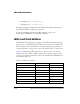
SRAM Interface
The board has a 1M x 16-bit flash memory connected to the processor’s
asynchronous memory interface (AMI). The SRAM can be accessed via
the asynchronous memory select 3 pin. It allows access to 16 bits of data
and interfaces to address line 0 through 19 of the processor.
An example program is included in the EZ-Board installation directory to
demonstrate how to setup and access the SRAM interface. For more infor-