
Datasheet


ADSP-21479 EZ-Board Evaluation System Manual 1-15
Using ADSP-21479 EZ-Board
Access to the shift register of the processor is available via the shift register
interface connector (
P4). Users can use a standard 2 mm ribbon cable if
they require off-board capabilities. For more information, see “Shift Reg-
ister Interface Connector (P4)” on page 2-27.
S/PDIF Interface
The ADSP-21479 processor has a built-in S/PDIF transmitter and
receiver for digital audio applications. The EZ-Board supports the S/PDIF
interface and brings out both the transmitter and receiver via RCA con-
nectors J6 and J7, respectively. The S/PDIF’s in and out pins are
connected by DAI pins via switches SW1 and SW7:
• DAI pin 1 (DAI_P1) as SPDIF_OUT
• DAI pin 18 (DPI_P18) as SPDIF_IN
SW1 and SW7 can be turned OFF to disconnect the DAI pins from the RCA
connectors if the pins are used on the expansion II interface. See “DAI [1–
8] Enable Switch (SW1)” on page 2-8 and “DAI [17–20] Enable Switch
(SW7)” on page 2-11 for more information.
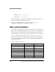
Audio Interface
The AD1939 device is a high-performance, single-chip codec featuring
eight digital-to-analog converters (DACs) for audio output and four ana-
log-to-digital converters (ADCs) for audio input. This translates to four
stereo channels of audio out and two stereo channels of audio in.
The codec can input and output data at a sample rate of up to 192 kHz on
all channels.
The analog audio channels are available via single-ended RCA connectors
(J4 and J5) or differential DB25 connectors (P8 and P9). By default, the
EZ-Board is shipped with the RCA connectors used by the AD1939 codec