
Datasheet


ADSP-21479 EZ-Board Evaluation System Manual 1-17
Using ADSP-21479 EZ-Board
serial ports. Connecting the codec in this manner enables a flexible audio
sample rate and allows the processor to run at the maximum core
frequency.
The audio interface also has a 3.5 mm connector (
J8) for headphones. The
headphones share the output with the external DAC5 and DAC6 circuits of
the analog audio interface. Switch SW23 must be enabled for the head-
phones. A volume control potentiometer (R493) is used to increase or
decrease the headphone’s volume. For more information, see “Headphone
Enable Switch (SW23)” on page 2-18.
Example programs are included in the EZ-Board installation directory to
demonstrate how to configure and use the board’s analog audio interface.
The DAI and DPI pins going to the AD1939 device can be disabled, then
used again on the expansion II interface. Refer to “DAI Interface” on
page 2-3 and “DPI Interface” on page 2-4 for more information about the
DAI and DPI switches.
UART Interface
The ADSP-21479 processor features a built-in universal asynchronous
receiver and transmitter (UART). The UART interface supports full
RS-232 functionality via the Analog Devices 3.3V ADM3202 line driver
and receiver (
U8). The UART signals are available on the EZ-Board via a
DIP switch (SW14). The UART signals routed through the DIP switch can
be disconnected from the respective DPI interface and used on the expan-
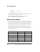
sion II interface. The following DPI pins are used for the RS-232
interface.
• DPI pin 9 (DPI_P9) as UART_TX
• DPI pin 10 (DPI_P10) as UART_RX