
Datasheet


LEDs and Push Buttons
1-18 ADSP-21479 EZ-Board Evaluation System Manual
• DPI pin 11 (
DPI_P11) as UART_RTS
• DPI pin 12 (DPI_P12) as UART_CTS
Example programs are included in the EZ-Board installation directory to
demonstrate UART and RS-232 operations.
For more information about the UART interface, refer to the
ADSP-214xx SHARC Processor Hardware Reference.
LEDs and Push Buttons
The EZ-Board has eight general-purpose user LEDs connected directly to
the processor, one EZ-Board power LED, and one board reset LED. The
EZ-board also has five push buttons: four general-purpose push buttons
connected directly to the processor and one push button for a board reset.
Table 1-3 summarizes LED connections to the processor. To use the
LEDs connected to DAI or DPI, configure the respective registers of the
processor. For more information, refer to the ADSP-214xx SHARC Proces-
sor Hardware Reference.
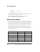
Table 1-3. LED Connections
LED Reference Designator Processor Pin Connected via Switch
LED1 DPI_P6 SW3.6
LED2 DPI_P13 SW14.5
LED3 DPI_P14 SW14.6
LED4 DAI_P3 SW1.3
LED5 DAI_P4 SW1.4
LED6 DAI_P15 SW2.7
LED7 DAI_P16 SW2.8
LED8 DAI_P17 SW7.1