
Datasheet


ADSP-21479 EZ-Board Evaluation System Manual 2-5
ADSP-21479 EZ-Board Hardware Reference
tors through which the pins are connected to the peripherals, and default
switch settings.
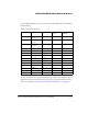
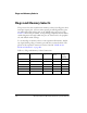
To use the DPI on the expansion II interface, disable any signal driving a
DPI pin with the associated switch. The pinout of the expansion connec-
tors can be found in “ADSP-21479 EZ-Board Schematic” on page B-1.
Table 2-2. DPI Connections
DPI Pin Peripheral Peripheral Net Connected via
Switch
Switch Setting
(Default)
DPI_P1 SPI memory/
AD1939
SPI_MOSI SW3.1 ON
DPI_P2 SPI memory/
AD1939
SPI_MISO SW3.2 ON
DPI_P3 SPI memory/
AD1939
SPI_CLK SW3.3 ON
DPI_P4 AD1939 AD1939_CS SW3.4 ON
DPI_P5 SPI memory SPI_CS SW3.5 ON
DPI_P6 LEDs LED1 SW3.6 ON
DPI_P7 Internal testing Not used SW3.7 OFF
DPI_P8 Not used Not used SW3.8 OFF
DPI_P9 UART UART_TX SW14.1 ON
DPI_P10 UART UART_RX SW14.2 ON
DPI_P11 UART UART_RTS SW14.3 OFF
DPI_P12 UART UART_CTS SW14.4 OFF
DPI_P13
UART LED2 SW14.5 ON
DPI_P14 UART LED3 SW14.6 ON