
Datasheet


Flags and Memory Selects
2-6 ADSP-21479 EZ-Board Evaluation System Manual
Flags and Memory Selects
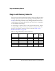
The processor has four asynchronous memory selects, four flag pins, three
interrupt request pins, and one timer expired pin. All flag/memory pins
are multi-functional and depend on the ADSP-21479 processor setup.
Table 2-3 shows the pin names, corresponding peripheral and net names,
switch designators through which the pins are connected to the peripher-
als, and default switch settings.
To use the flags or memory selects on the expansion II interface, disable
any signal driving a flag or memory pin with the associated switch. The
pinout of the expansion connectors can be found in “ADSP-21479
EZ-Board Schematic” on page B-1.
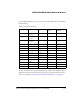
Table 2-3. Flags and Memory Select Connections
Flag/Memory Pin Peripheral Peripheral Net Connected via
Switch
Switch
Setting
(Default)
MS0 SDRAM SDRAM_CS SW13.1 ON
MS1 Parallel flash memory FLASH_CS SW13.2 ON
FLAG1/IRQ1 Push buttons PB1 SW13.3 ON
FLAG2/IRQ2/MS2 Push buttons PB2 SW13.4 ON
FLAG3/MS3 SRAM SRAM_CS SW13.5 ON
WDTRSTO_Z
Reset Supervisory IC WDTRSTO SW13.6 OFF